Lexus ES: Lost Communication with Steering Heater ECU (B14B7)
DESCRIPTION
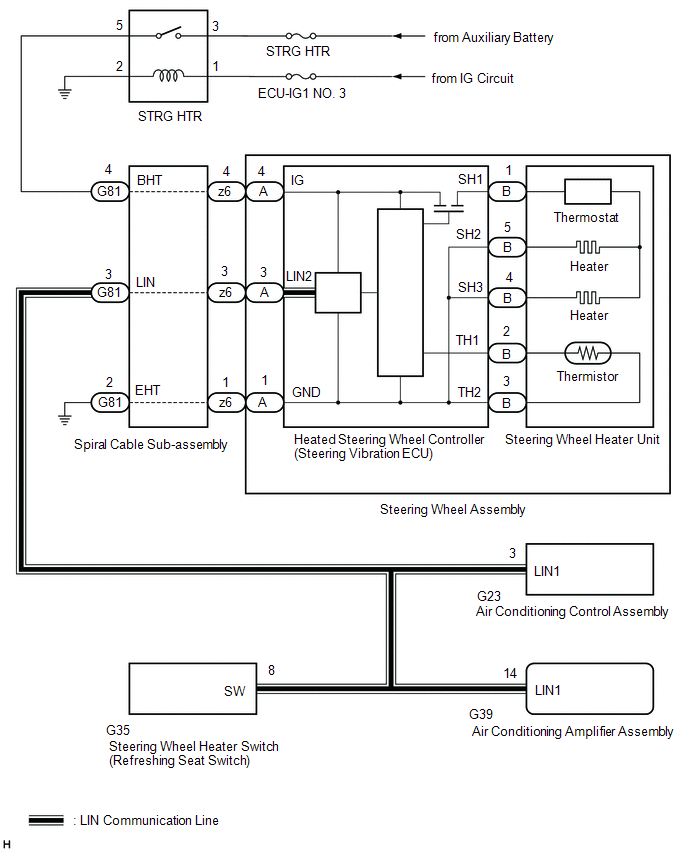
The heated steering wheel controller (steering vibration ECU) communicates with the air conditioning amplifier assembly via LIN communication.
B14B7 is output when a communication malfunction is detected with the air conditioner amplifier assembly and heated steering wheel controller (steering vibration ECU).
| DTC No. | Detection Item | DTC Detection Condition | Trouble Area |
|---|---|---|---|
| B14B7 | Lost Communication with Steering Heater ECU |
|
|
WIRING DIAGRAM
CAUTION / NOTICE / HINT
NOTICE:
- Inspect the fuses for circuits related to this system before performing the following procedure.
-
The vehicle is equipped with a Supplemental Restraint System (SRS) which includes components such as airbags. Before servicing (including removal or installation of parts), be sure to read the precaution for Supplemental Restraint System.
Click here
.gif)
PROCEDURE
| 1. | CHECK FOR DTCs |
(a) Check for DTCs.
Body Electrical > Air Conditioner > Trouble Codes| Result | Proceed to |
|---|---|
| Only DTC B14B7 is output | A |
| DTC B14B7 and B14B2 are output | B |
| DTC B14B7 and B14B5 are output | C |
| B | .gif) | GO TO STEP 5 |
| C | | GO TO STEP 9 |
|
.gif)
| 2. | CHECK HARNESS OR CONNECTOR (HEATED STEERING WHEEL CONTROLLER (STEERING VIBRATION ECU) POWER SOURCE CIRCUIT) |
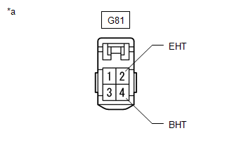
| (a) Disconnect the G81 spiral cable with sensor sub-assembly connector. |
|
(b) Measure the voltage according to the value(s) in the table below.
Standard Voltage:
| Tester Connection | Condition | Specified Condition |
|---|---|---|
| G81-4 (BHT) - Body ground | Power switch on (IG) | 11 to 14 V |
| G81-4 (BHT) - Body ground | Power switch off | Below 1 V |
(c) Measure the resistance according to the value(s) in the table below.
Standard Resistance:
| Tester Connection | Condition | Specified Condition |
|---|---|---|
| G81-2 (EHT) - Body ground | Always | Below 1 Ω |
| NG | | REPAIR OR REPLACE HARNESS OR CONNECTOR (HEATED STEERING WHEEL CONTROLLER (STEERING VIBRATION ECU) POWER SOURCE CIRCUIT) |
|
| 3. | INSPECT SPIRAL CABLE SUB-ASSEMBLY |
(a) Remove the spiral cable sub-assembly.
Click here
(b) Inspect the spiral cable sub-assembly.
Click here
| NG | | REPLACE SPIRAL CABLE SUB-ASSEMBLY |
|
| 4. | CHECK HARNESS OR CONNECTOR (SPIRAL CABLE WITH SENSOR SUB-ASSEMBLY - AIR CONDITIONING AMPLIFIER ASSEMBLY) |
(a) Disconnect the G81 spiral cable with sensor sub-assembly connector.
(b) Disconnect the G39 air conditioning amplifier assembly connector.
(c) Disconnect the G23 air conditioning control assembly connector.
(d) Disconnect the G35 Steering Wheel Heater Switch (Refreshing Seat Switch) connector.
(e) Measure the resistance according to the value(s) in the table below.
Standard Resistance:
| Tester Connection | Condition | Specified Condition |
|---|---|---|
| G81-3 (LIN) - G39-14 (LIN1) | Always | Below 1 Ω |
| OK | | REPLACE HEATED STEERING WHEEL CONTROLLER (STEERING VIBRATION ECU) |
| NG | | REPAIR OR REPLACE HARNESS OR CONNECTOR (SPIRAL CABLE WITH SENSOR SUB-ASSEMBLY - AIR CONDITIONING AMPLIFIER ASSEMBLY) |
| 5. | CHECK HARNESS OR CONNECTOR (SPIRAL CABLE WITH SENSOR SUB-ASSEMBLY - AIR CONDITIONING AMPLIFIER ASSEMBLY AND AIR CONDITIONING CONTROL ASSEMBLY) |
(a) Disconnect the G81 spiral cable with sensor sub-assembly connector.
(b) Disconnect the G39 air conditioning amplifier assembly connector.
(c) Disconnect the G23 air conditioning control assembly connector.
(d) Disconnect the G35 Steering Wheel Heater Switch (Refreshing Seat Switch) connector.
(e) Measure the resistance according to the value(s) in the table below.
Standard Resistance:
| Tester Connection | Condition | Specified Condition |
|---|---|---|
| G81-3 (LIN) - G39-14 (LIN1) | Always | Below 1 Ω |
| G81-3 (LIN), G39-14 (LIN1) or G23-3 (LIN1) - Body ground | Always | 10 kΩ or higher |
| NG | | REPAIR OR REPLACE HARNESS OR CONNECTOR (SPIRAL CABLE WITH SENSOR SUB-ASSEMBLY - AIR CONDITIONING AMPLIFIER ASSEMBLY AND AIR CONDITIONING CONTROL ASSEMBLY) |
|
| 6. | CHECK FOR DTCs |
(a) Clear the DTCs.
Body Electrical > Air Conditioner > Clear DTCs(b) Disconnect the G23 air conditioning control assembly connector.
(c) Make sure that the DTC detection conditions are met.
HINT:
If the detection conditions are not met, the system cannot detect the malfunction.
(d) Check for DTCs.
Body Electrical > Air Conditioner > Trouble Codes| Result | Proceed to |
|---|---|
| Only DTC B14B2 is output | A |
| DTC B14B2 and B14B7 are output | B |
| A | | REPLACE AIR CONDITIONING CONTROL ASSEMBLY |
|
| 7. | CHECK FOR DTCs |
(a) Clear the DTCs.
Body Electrical > Air Conditioner > Clear DTCs(b) Disconnect the z6 spiral cable with sensor sub-assembly connector.
(c) Make sure that the DTC detection conditions are met.
HINT:
If the detection conditions are not met, the system cannot detect the malfunction.
(d) Check for DTCs.
Body Electrical > Air Conditioner > Trouble Codes| Result | Proceed to |
|---|---|
| Only DTC B14B7 is output | A |
| DTC B14B2 and B14B7 are output | B |
| A | | REPLACE HEATED STEERING WHEEL CONTROLLER (STEERING VIBRATION ECU) |
|
| 8. | CHECK FOR DTCs |
(a) Clear the DTCs.
Body Electrical > Air Conditioner > Clear DTCs(b) Disconnect the G81 spiral cable with sensor sub-assembly connector.
(c) Make sure that the DTC detection conditions are met.
HINT:
If the detection conditions are not met, the system cannot detect the malfunction.
(d) Check for DTCs.
Body Electrical > Air Conditioner > Trouble Codes| Result | Proceed to |
|---|---|
| Only DTC B14B7 is output | A |
| DTC B14B2 and B14B7 are output | B |
| A | | REPLACE SPIRAL CABLE SUB-ASSEMBLY |
| B | | REPLACE AIR CONDITIONING AMPLIFIER ASSEMBLY |
| 9. | CHECK HARNESS OR CONNECTOR (SPIRAL CABLE WITH SENSOR SUB-ASSEMBLY - AIR CONDITIONING AMPLIFIER ASSEMBLY AND STEERING WHEEL HEATER SWITCH) |
(a) Disconnect the G81 spiral cable with sensor sub-assembly connector.
(b) Disconnect the G39 air conditioning amplifier assembly connector.
(c) Disconnect the G35 Steering Wheel Heater Switch (Refreshing Seat Switch) connector.
(d) Disconnect the G23 air conditioning control assembly connector.
(e) Measure the resistance according to the value(s) in the table below.
Standard Resistance:
| Tester Connection | Condition | Specified Condition |
|---|---|---|
| G81-3 (LIN) - G39-14 (LIN1) | Always | Below 1 Ω |
| G81-3 (LIN), G39-14 (LIN1) or G35-8 (SW) - Body ground | Always | 10 kΩ or higher |
| NG | | REPAIR OR REPLACE HARNESS OR CONNECTOR (SPIRAL CABLE WITH SENSOR SUB-ASSEMBLY - AIR CONDITIONING AMPLIFIER ASSEMBLY AND STEERING WHEEL HEATER SWITCH) |
|
| 10. | CHECK FOR DTCs |
(a) Clear the DTCs.
Body Electrical > Air Conditioner > Clear DTCs(b) Disconnect the G35 Steering Wheel Heater Switch (Refreshing Seat Switch) connector.
(c) Make sure that the DTC detection conditions are met.
HINT:
If the detection conditions are not met, the system cannot detect the malfunction.
(d) Check for DTCs.
Body Electrical > Air Conditioner > Trouble Codes| Result | Proceed to |
|---|---|
| Only DTC B14B5 is output | A |
| DTC B14B5 and B14B7 are output | B |
| A | | REPLACE STEERING WHEEL HEATER SWITCH (REFRESHING SEAT SWITCH) |
|
| 11. | CHECK FOR DTCs |
(a) Clear the DTCs.
Body Electrical > Air Conditioner > Clear DTCs(b) Disconnect the z6 spiral cable with sensor sub-assembly connector.
(c) Make sure that the DTC detection conditions are met.
HINT:
If the detection conditions are not met, the system cannot detect the malfunction.
(d) Check for DTCs.
Body Electrical > Air Conditioner > Trouble Codes| Result | Proceed to |
|---|---|
| Only DTC B14B7 is output | A |
| DTC B14B5 and B14B7 are output | B |
| A | | REPLACE HEATED STEERING WHEEL CONTROLLER (STEERING VIBRATION ECU) |
|
| 12. | CHECK FOR DTCs |
(a) Clear the DTCs.
Body Electrical > Air Conditioner > Clear DTCs(b) Disconnect the G81 spiral cable with sensor sub-assembly connector.
(c) Make sure that the DTC detection conditions are met.
HINT:
If the detection conditions are not met, the system cannot detect the malfunction.
(d) Check for DTCs.
Body Electrical > Air Conditioner > Trouble Codes| Result | Proceed to |
|---|---|
| Only DTC B14B7 is output | A |
| DTC B14B5 and B14B7 are output | B |
| A | | REPLACE SPIRAL CABLE SUB-ASSEMBLY |
| B | | REPLACE AIR CONDITIONING AMPLIFIER ASSEMBLY |
READ NEXT:
 Steering Wheel does not Heat Up When Heated Steering Wheel Switch is Pressed
DESCRIPTION Click here WIRING DIAGRAM Click here CAUTION / NOTICE / HINT NOTICE: The vehicle is equipped with a Supplemental Restraint System (SRS) which includes components such as airbags. Befor
Multiplex Tilt And Telescopic Ecu
ComponentsCOMPONENTS ILLUSTRATION *1 LOWER STEERING COLUMN COVER SUB-ASSEMBLY *2 MULTIPLEX TILT AND TELESCOPIC ECU RemovalREMOVAL PROCEDURE 1. CHANGE POWER TILT AND POWER TELESCOPIC STE
SEE MORE:
Heated steering wheel/seat heaters/
seat ventilators
Heated steering wheel
Warms up the grip of the steering wheel
Seat heaters
Warm up the seat upholstery
Seat ventilators
Maintain good air flow by sucking air
into the seats
Press the "MENU" button on the
Remote Touch and select "Climate"
to display the air conditioning control
s
Assist Map Number Mismatch (C1582)
DESCRIPTION When an incorrect ECM, skid control ECU (brake actuator assembly) or AVS ECU (Absorber control ECU) (w/ Adaptive Variable Suspension System) is installed after the assist map has been written to the power steering ECU (rack and pinion power steering gear assembly), DTC C1582 is stored be
