Lexus ES: Multiplex Tilt And Telescopic Ecu
Components
COMPONENTS
ILLUSTRATION
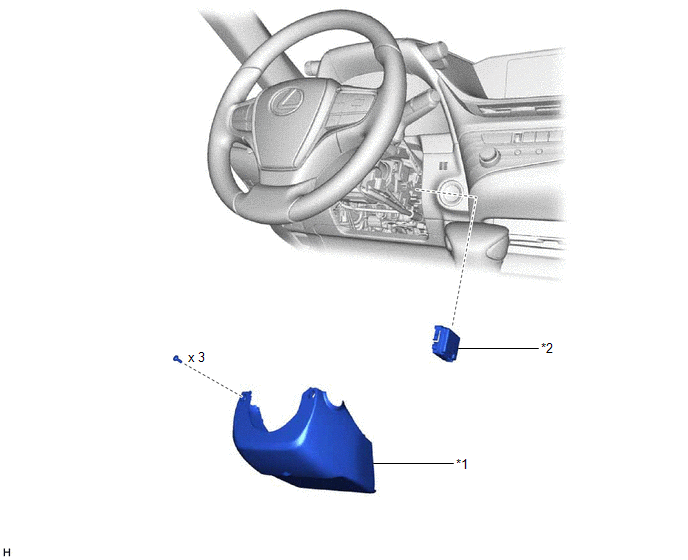
| *1 | LOWER STEERING COLUMN COVER SUB-ASSEMBLY | *2 | MULTIPLEX TILT AND TELESCOPIC ECU |
Removal
REMOVAL
PROCEDURE
1. CHANGE POWER TILT AND POWER TELESCOPIC STEERING COLUMN SYSTEM SETTINGS
Click here .gif)
2. REMOVE LOWER STEERING COLUMN COVER SUB-ASSEMBLY
Click here
3. REMOVE MULTIPLEX TILT AND TELESCOPIC ECU
(a) Disengage each connector and disengage each wire harness clamp from the steering column assembly.
(b) Disconnect the connector.
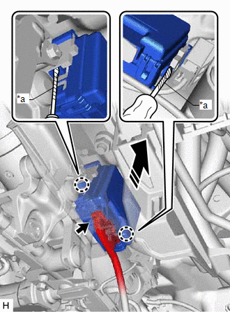
| *a | Protective Tape |
 | Remove in this direction |
(c) Using a screwdriver with its tip wrapped with protective tape, disengage the 2 claws and remove the multiplex tilt and telescopic ECU.
Installation
INSTALLATION
PROCEDURE
1. INSTALL MULTIPLEX TILT AND TELESCOPIC ECU
(a) Engage the 2 claws to install the multiplex tilt and telescopic ECU.
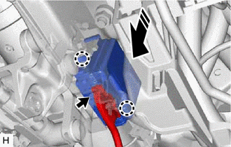
.png) | Install in this direction |
(b) Connect the connector.
(c) Connect each connector and engage each wire harness clamp to the steering column assembly.
2. INSTALL LOWER STEERING COLUMN COVER SUB-ASSEMBLY
Click here .gif)
3. CUSTOMIZE POWER TILT AND POWER TELESCOPIC STEERING COLUMN SYSTEM
Click here
READ NEXT:
 Precaution
PRECAUTION PRECAUTION FOR DISCONNECTING CABLE FROM NEGATIVE AUXILIARY BATTERY TERMINAL NOTICE: When disconnecting the cable from the negative (-) auxiliary battery terminal, initialize the following s
Parts Location
PARTS LOCATION ILLUSTRATION *1 TILT AND TELESCOPIC SWITCH *2 STEERING COLUMN ASSEMBLY - TILT MOTOR - TELESCOPIC MOTOR *3 NO. 1 ENGINE ROOM RELAY BLOCK AND NO. 1 JUNCTION BLOCK ASSEMBLY
SEE MORE:
Inspection
INSPECTION PROCEDURE 1. INSPECT FUEL LID OPENER SWITCH (TRUNK AND FUEL SWITCH ASSEMBLY) (a) Check the switch. (1) Measure the resistance according to the value(s) in the table below. Standard Resistance: Tester Connection Condition Specified Condition 2 (B) - 3 (L) Pressed (On) Be
Operation Check
OPERATION CHECK CHECK DOOR OPEN LINKED WIPER SUSPEND FUNCTION (w/ Auto Wiper System) (a) Continuously apply water to the windshield glass in front of the rain sensor. (b) Turn the engine switch on (IG). (c) Move the windshield wiper switch assembly to the AUTO position and check that the front wiper
