Lexus ES: Shift Paddle Switch Circuit
DESCRIPTION
Moving the shift lever to S enables the shift range to be selected. The shift range can be selected by operating the "+" or "-" shift paddle switch.
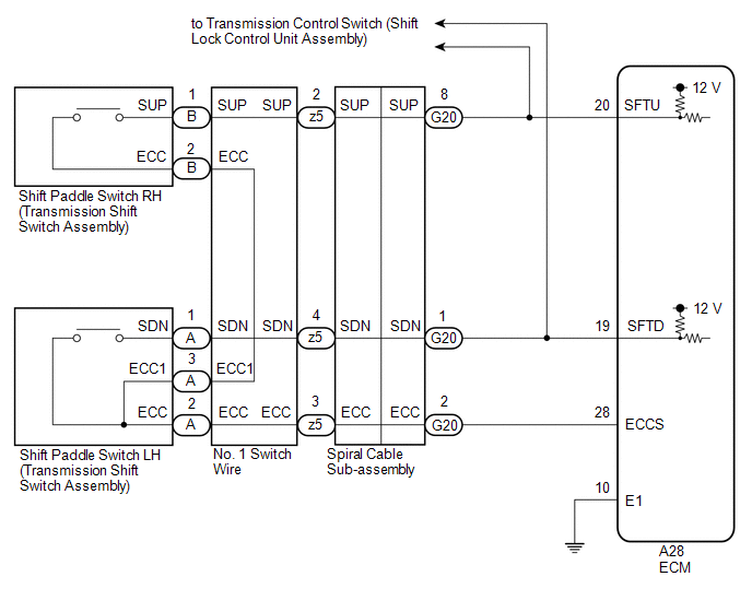
WIRING DIAGRAM
CAUTION / NOTICE / HINT
NOTICE:
After turning the engine switch off, waiting time may be required before disconnecting the cable from the negative (-) battery terminal. Therefore, make sure to read the disconnecting the cable from the negative (-) battery terminal notices before proceeding with work.
Click here .gif)
PROCEDURE
| 1. | READ VALUE USING TECHSTREAM (SPORT SHIFT SWITCH STATUS) |
(a) Connect the Techstream to the DLC3.
(b) Turn the engine switch on (IG).
(c) Turn the Techstream on.
(d) Enter the following menus: Powertrain / Engine / Data List.
(e) According to the display on the Techstream, read the Data List.
Powertrain > Engine > Data List| Tester Display | Measurement Item | Range | Normal Condition | Diagnostic Note |
|---|---|---|---|---|
| Sport Shift Up SW | Sport shift up switch status | ON or OFF |
| - |
| Sport Shift Down SW | Sport shift down switch status | ON or OFF |
| - |
| Tester Display |
|---|
| Sport Shift Up SW |
| Sport Shift Down SW |
| Result | Proceed to |
|---|---|
| Data List values are normal | A |
| Data List values are not normal | B |
| A | .gif) | CHECK FOR INTERMITTENT PROBLEMS |
|
.gif)
| 2. | CHECK HARNESS AND CONNECTOR (SHIFT PADDLE SWITCH CIRCUIT) |
(a) Disconnect the A28 ECM connector.
(b) Measure the resistance according to the value(s) in the table below.
Standard Resistance:
| Tester Connection | Condition | Specified Condition |
|---|---|---|
| A28-20 (SFTU) - A28-28 (ECCS) | "+" (Up shift) shift paddle switch operated and held | Below 2.5 Ω |
| "+" (Up shift) shift paddle switch not operated | 1 MΩ or higher | |
| A28-19 (SFTD) - A28-28 (ECCS) | "-" (Down shift) shift paddle switch operated and held | Below 2.5 Ω |
| "-" (Down shift) shift paddle switch not operated | 1 MΩ or higher |
| NG | | GO TO STEP 4 |
|
| 3. | CHECK HARNESS AND CONNECTOR (ECM - BODY GROUND) |
(a) Disconnect the A28 ECM connector.
(b) Measure the resistance according to the value(s) in the table below.
Standard Resistance:
| Tester Connection | Condition | Specified Condition |
|---|---|---|
| A28-10 (E1) - Body ground | Always | Below 1 Ω |
| OK | | PROCEED TO NEXT SUSPECTED AREA SHOWN IN PROBLEM SYMPTOMS TABLE |
| NG | | REPAIR OR REPLACE HARNESS OR CONNECTOR (ECM - BODY GROUND) |
| 4. | CHECK HARNESS AND CONNECTOR (SPIRAL CABLE SUB-ASSEMBLY - ECM) |
(a) Disconnect the G20 spiral cable sub-assembly connector.
(b) Disconnect the A28 ECM connector.
(c) Measure the resistance according to the value(s) in the table below.
Standard Resistance:
| Tester Connection | Condition | Specified Condition |
|---|---|---|
| A28-20 (SFTU) - G20-8 (SUP) | Always | Below 1 Ω |
| A28-19 (SFTD) - G20-1 (SDN) | Always | Below 1 Ω |
| A28-28 (ECCS) - G20-2 (ECC) | Always | Below 1 Ω |
| A28-20 (SFTU) or G20-8 (SUP) - Body ground | Always | 10 kΩ or higher |
| A28-19 (SFTD) or G20-1 (SDN) - Body ground | Always | 10 kΩ or higher |
| A28-28 (ECCS) or G20-2 (ECC) - Body ground | Always | 10 kΩ or higher |
| NG | | REPAIR OR REPLACE HARNESS OR CONNECTOR (SPIRAL CABLE SUB-ASSEMBLY - ECM) |
|
| 5. | INSPECT SPIRAL CABLE SUB-ASSEMBLY |
(a) Inspect the spiral cable sub-assembly.
Click here
| NG | | REPLACE SPIRAL CABLE SUB-ASSEMBLY |
|
| 6. | INSPECT SHIFT PADDLE SWITCH LH (TRANSMISSION SHIFT SWITCH ASSEMBLY) |
| (a) Remove the shift paddle switch LH (transmission shift switch assembly). Click here |
|
.png)
(b) Measure the resistance according to the value(s) in the table below.
Standard Resistance:
| Tester Connection | Condition | Specified Condition |
|---|---|---|
| A-1 (SDN) - A-2 (ECC) | "-" (Down shift) shift paddle switch operated and held | Below 2.5 Ω |
| "-" (Down shift) shift paddle switch not operated | 1 MΩ or higher | |
| A-1 (SDN) - A-3 (ECC1) | "-" (Down shift) shift paddle switch operated and held | Below 2.5 Ω |
| "-" (Down shift) shift paddle switch not operated | 1 MΩ or higher |
| NG | | REPLACE SHIFT PADDLE SWITCH LH (TRANSMISSION SHIFT SWITCH ASSEMBLY) |
|
| 7. | INSPECT SHIFT PADDLE SWITCH RH (TRANSMISSION SHIFT SWITCH ASSEMBLY) |
| (a) Remove the shift paddle switch RH (transmission shift switch assembly). Click here |
|
.png)
(b) Measure the resistance according to the value(s) in the table below.
Standard Resistance:
| Tester Connection | Condition | Specified Condition |
|---|---|---|
| B-1 (SUP) - B-2 (ECC) | "+" (Up shift) shift paddle switch operated and held | Below 2.5 Ω |
| "+" (Up shift) shift paddle switch not operated | 1 MΩ or higher |
| NG | | REPLACE SHIFT PADDLE SWITCH RH (TRANSMISSION SHIFT SWITCH ASSEMBLY) |
|
| 8. | INSPECT NO. 1 SWITCH WIRE |
| (a) Install the transmission shift switch assembly. Click here |
|
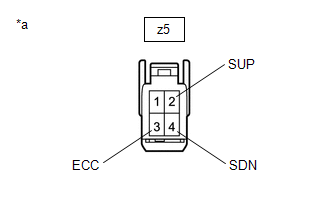
(b) Disconnect the z5 No. 1 switch wire connector.
(c) Measure the resistance according to the value(s) in the table below.
Standard Resistance:
| Tester Connection | Condition | Specified Condition |
|---|---|---|
| z5-2 (SUP) - z5-3 (ECC) | "+" (Up shift) shift paddle switch operated and held | Below 2.5 Ω |
| "+" (Up shift) shift paddle switch not operated | 1 MΩ or higher | |
| z5-4 (SDN) - z5-3 (ECC) | "-" (Down shift) shift paddle switch operated and held | Below 2.5 Ω |
| "-" (Down shift) shift paddle switch not operated | 1 MΩ or higher |
| OK | | PROCEED TO NEXT SUSPECTED AREA SHOWN IN PROBLEM SYMPTOMS TABLE |
| NG | | REPLACE NO. 1 SWITCH WIRE |
READ NEXT:
 System Diagram
SYSTEM DIAGRAM
Terminals Of Ecm
TERMINALS OF ECM ECM HINT: The standard voltage and resistance of each ECM terminal is shown in the table below. In the table, first follow the information under "Condition". Look under "Terminal No.
Transmission Control Switch Circuit
DESCRIPTION When the shift lever is in S and moved toward "-" or "+", it is possible to select different shift ranges (S1 to S8). Moving the shift lever toward "+" increases the shift range by one, an
SEE MORE:
Registration
REGISTRATION PROCEDURE 1. REGISTER TRANSMITTER CODE HINT:
The vehicle garage door opener records transmitter codes for systems such as garage doors, gates, entry gates, door locks, home lighting systems, security systems or other transmitter code based systems.
The garage door opener is built i
Image from Camera for Panoramic View Monitor is Abnormal
DESCRIPTION The display signal from each camera is transmitted to the multi-display assembly via the parking assist ECU. WIRING DIAGRAM CAUTION / NOTICE / HINT NOTICE:
When "!" is displayed on the multi-display assembly after the cable is disconnected from the negative (-) battery terminal, cor
