Lexus ES: Steering Wheel does not Heat Up When Heated Steering Wheel Switch is Pressed
DESCRIPTION
Click here .gif)
WIRING DIAGRAM
Click here
CAUTION / NOTICE / HINT
NOTICE:
The vehicle is equipped with a Supplemental Restraint System (SRS) which includes components such as airbags. Before servicing (including removal or installation of parts), be sure to read the precaution for Supplemental Restraint System.
Click here
PROCEDURE
| 1. | INSPECT STEERING WHEEL ASSEMBLY (THERMOSTAT, HEATER AND THERMISTOR) |
| (a) Disconnect the B heated steering wheel controller (steering vibration ECU) connector. |
|
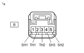
(b) Measure the resistance according to the value(s) in the table below.
Standard Resistance (for F SPORT Models):
| Tester Connection | Condition | Specified Condition |
|---|---|---|
| B-1 (SH1) - B-4 (SH3) | 20°C (68°F) | 2.52 to 3.00 Ω |
| B-1 (SH1) - B-5 (SH2) | 20°C (68°F) | 2.52 to 3.00 Ω |
| B-2 (TH1) - B-3 (TH2) | 10 to 30°C (50 to 86°F) | 4.228 to 8.701 kΩ |
Standard Resistance (except F SPORT Models):
| Tester Connection | Condition | Specified Condition |
|---|---|---|
| B-1 (SH1) - B-4 (SH3) | 20°C (68°F) | 2.33 to 2.77 Ω |
| B-1 (SH1) - B-5 (SH2) | 20°C (68°F) | 2.33 to 2.77 Ω |
| B-2 (TH1) - B-3 (TH2) | 10 to 30°C (50 to 86°F) | 4.228 to 8.701 kΩ |
| OK | .gif) | REPLACE HEATED STEERING WHEEL CONTROLLER (STEERING VIBRATION ECU) |
| NG | | REPLACE STEERING WHEEL ASSEMBLY |
READ NEXT:
 Multiplex Tilt And Telescopic Ecu
ComponentsCOMPONENTS ILLUSTRATION *1 LOWER STEERING COLUMN COVER SUB-ASSEMBLY *2 MULTIPLEX TILT AND TELESCOPIC ECU RemovalREMOVAL PROCEDURE 1. CHANGE POWER TILT AND POWER TELESCOPIC STE
Precaution
PRECAUTION PRECAUTION FOR DISCONNECTING CABLE FROM NEGATIVE AUXILIARY BATTERY TERMINAL NOTICE: When disconnecting the cable from the negative (-) auxiliary battery terminal, initialize the following s
SEE MORE:
Malfunction in Rear Speed Sensor RH Circuit (C1403,C1404)
DESCRIPTION Refer to DTCs C1415 and C1416. Click here DTC No. Detection Item INF Code DTC Detection Condition Trouble Area MIL Note C1403 Malfunction in Rear Speed Sensor RH Circuit 521 522 527
INF Code: 521
At a vehicle speed of 10 km/h (6 mph) or more, output volta
Disassembly
DISASSEMBLY PROCEDURE 1. REMOVE FRONT DRIVE SHAFT OIL SEAL RH (a) Hold the differential case assembly in a vise between aluminum plates. NOTICE: Do not overtighten the vise. (b) Using SST, remove the front drive shaft oil seal RH from the differential case assembly. SST: 09308-00010 N
