Lexus ES: Installation
INSTALLATION
PROCEDURE
1. INSTALL MULTI-DISPLAY ASSEMBLY
2. INSTALL CLOCK ASSEMBLY
Click here .gif)
3. INSTALL MULTI-MEDIA MODULE COVER
(a) for 8 Inch Display:
(1) Engage the 6 guides and 3 claws as shown in the illustration.
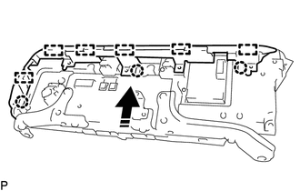
.png) | Install in this Direction |
(2) Install the multi-media module cover with the 5 screws.
(b) for 12.3 Inch Display:
(1) Engage the 7 claws.
(2) Install the multi-media module cover with the 4 screws.
4. INSTALL NO. 1 SUB-CLUSTER MODULE PANEL
(a) for 8 Inch Display:
(1) Install the No. 1 sub-cluster module panel with the 3 screws.
(b) for 12.3 Inch Display:
(1) Engage the 2 guides.
(2) Install the No. 1 sub-cluster module panel with the 3 screws.
5. INSTALL MULTI-DISPLAY ASSEMBLY WITH CLOCK
(a) Connect each connector.
(b) Engage the clamp.
(c) Push the multi-display assembly with clock as shown in the illustration to engage the 4 clips.
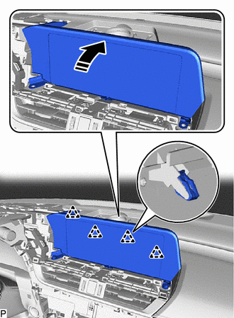
| | Install in this Direction |
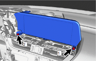
| (d) Install the multi-display assembly with clock with the 2 bolts. HINT: Install the bolts in the order shown in the illustration. |
|
6. INSTALL NO. 1 SPEAKER OPENING COVER ASSEMBLY
Click here
7. INSTALL UPPER INSTRUMENT PANEL FINISH PANEL SUB-ASSEMBLY
Click here
8. INSTALL INSTRUMENT CLUSTER FINISH PANEL SUB-ASSEMBLY (w/o Headup Display)
Click here
9. INSTALL INSTRUMENT CLUSTER FINISH PANEL SUB-ASSEMBLY (w/ Headup Display)
Click here
10. INSTALL NO. 2 INSTRUMENT CLUSTER MOULDING
Click here
11. INSTALL LOWER INSTRUMENT PANEL SUB-ASSEMBLY
Click here
12. INSTALL NO. 1 INSTRUMENT CLUSTER MOULDING
Click here
13. INSTALL LOWER INSTRUMENT PANEL FINISH PANEL SUB-ASSEMBLY
Click here
14. INSTALL NO. 1 INSTRUMENT PANEL UNDER COVER SUB-ASSEMBLY
Click here
15. INSTALL INSTRUMENT SIDE PANEL LH
Click here
16. INSTALL FRONT DOOR OPENING TRIM COVER LH
Click here
17. INSTALL COWL SIDE TRIM BOARD LH
Click here
18. INSTALL FRONT DOOR SCUFF PLATE LH
Click here
19. INSTALL INSTRUMENT SIDE PANEL RH
Click here
20. INSTALL FRONT DOOR OPENING TRIM COVER RH
HINT:
Use the same procedure as for the LH side.
21. INSTALL COWL SIDE TRIM BOARD RH
HINT:
Use the same procedure as for the LH side.
22. INSTALL FRONT DOOR SCUFF PLATE RH
HINT:
Use the same procedure as for the LH side.
READ NEXT:
 Removal
REMOVAL PROCEDURE 1. REMOVE FRONT DOOR SCUFF PLATE LH Click here 2. REMOVE COWL SIDE TRIM BOARD LH Click here 3. REMOVE FRONT DOOR OPENING TRIM COVER LH Click here 4. REMOVE INSTRUMENT SIDE PANE
Components
COMPONENTS ILLUSTRATION *1 DEFROSTER NOZZLE ASSEMBLY *2 NAVIGATION ANTENNA ASSEMBLY *3 NAVIGATION ANTENNA ASSEMBLY WITH BRACKET *4 NAVIGATION ANTENNA BRACKET *5 NO. 2 SIDE DE
SEE MORE:
Replacement
REPLACEMENT PROCEDURE 1. REMOVE FRONT WHEEL OPENING EXTENSION PAD RH Click here 2. REMOVE FRONT WHEEL OPENING EXTENSION PAD LH Click here 3. REMOVE NO. 1 ENGINE UNDER COVER Click here 4. REMOVE NO. 2 ENGINE UNDER COVER ASSEMBLY Click here 5. REPLACE HYBRID TRANSAXLE FLUID Click here
Transmission Range Sensor "A" Circuit (PRNDL Input) Signal Compare Failure (P070562)
DESCRIPTION The shift lever position sensor sends 7 different switch signals to the hybrid vehicle control ECU. The hybrid vehicle control ECU uses these signals to detect the shift lever position (P, R, N or D). The hybrid vehicle control ECU also uses this information to determine the intended dir
