Lexus ES: Removal
REMOVAL
PROCEDURE
1. REMOVE FRONT DOOR SCUFF PLATE LH
Click here .gif)
2. REMOVE COWL SIDE TRIM BOARD LH
Click here
3. REMOVE FRONT DOOR OPENING TRIM COVER LH
Click here
4. REMOVE INSTRUMENT SIDE PANEL LH
Click here
5. REMOVE FRONT DOOR SCUFF PLATE RH
HINT:
Use the same procedure as for the LH side.
6. REMOVE COWL SIDE TRIM BOARD RH
HINT:
Use the same procedure as for the LH side.
7. REMOVE FRONT DOOR OPENING TRIM COVER RH
HINT:
Use the same procedure as for the LH side.
8. REMOVE INSTRUMENT SIDE PANEL RH
Click here
9. REMOVE NO. 1 INSTRUMENT PANEL UNDER COVER SUB-ASSEMBLY
Click here
10. REMOVE LOWER INSTRUMENT PANEL FINISH PANEL SUB-ASSEMBLY
Click here
11. REMOVE NO. 1 INSTRUMENT CLUSTER MOULDING
Click here
12. REMOVE LOWER INSTRUMENT PANEL SUB-ASSEMBLY
Click here
13. REMOVE NO. 2 INSTRUMENT CLUSTER MOULDING
Click here
14. REMOVE INSTRUMENT CLUSTER FINISH PANEL SUB-ASSEMBLY (w/o Headup Display)
Click here
15. REMOVE INSTRUMENT CLUSTER FINISH PANEL SUB-ASSEMBLY (w/ Headup Display)
Click here
16. REMOVE UPPER INSTRUMENT PANEL FINISH PANEL SUB-ASSEMBLY
Click here
17. REMOVE NO. 1 SPEAKER OPENING COVER ASSEMBLY
Click here
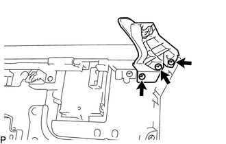
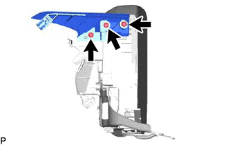
18. REMOVE MULTI-DISPLAY ASSEMBLY WITH CLOCK
| (a) Remove the 2 bolts. |
|
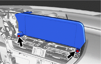
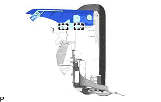
(b) Pull the multi-display assembly with clock as shown in the illustration to disengage the 4 clips.
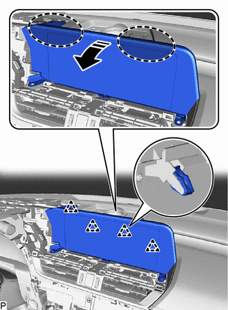
.png) | Place Hand Here |
.png) | Remove in this Direction |
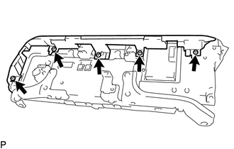
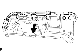
| (c) Disengage the clamp. |
|
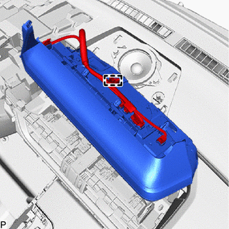
(d) Disconnect each connector and remove the multi-display assembly with clock.
19. REMOVE NO. 1 SUB-CLUSTER MODULE PANEL
(a) for 8 Inch Display:
| (1) Remove the 3 screws and No. 1 sub-cluster module panel. |
|
(b) for 12.3 Inch Display:
| (1) Remove the 3 screws. |
|
| (2) Disengage the 2 guides to remove the No. 1 sub-cluster module panel. |
|
20. REMOVE MULTI-MEDIA MODULE COVER
(a) for 8 Inch Display:
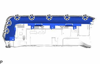
| (1) Remove the 5 screws. |
|
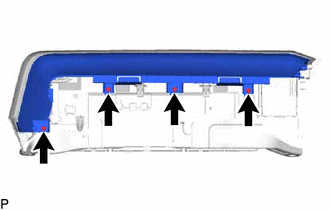
(2) Disengage the 3 claws and 6 guides as shown in the illustration to remove the multi-media module cover.
| | Remove in this Direction |
(b) for 12.3 Inch Display:
| (1) Remove the 4 screws. |
|
| (2) Disengage the 7 claws to remove the multi-media module cover. |
|
21. REMOVE CLOCK ASSEMBLY
Click here
22. REMOVE MULTI-DISPLAY ASSEMBLY
READ NEXT:
 Components
COMPONENTS ILLUSTRATION *1 DEFROSTER NOZZLE ASSEMBLY *2 NAVIGATION ANTENNA ASSEMBLY *3 NAVIGATION ANTENNA ASSEMBLY WITH BRACKET *4 NAVIGATION ANTENNA BRACKET *5 NO. 2 SIDE DE
Inspection
INSPECTION PROCEDURE 1. INSPECT NAVIGATION ANTENNA ASSEMBLY (w/o Manual (SOS) Switch) (a) Check that the navigation antenna assembly cable is properly installed and does not have any sharp bends, pinc
SEE MORE:
Luggage Compartment Door Outside Garnish
ComponentsCOMPONENTS ILLUSTRATION *1 LUGGAGE COMPARTMENT DOOR OUTSIDE GARNISH SUB-ASSEMBLY *2 CLIP ● Non-reusable part - - RemovalREMOVAL PROCEDURE 1. REMOVE REAR LIGHT ASSEMBLY LH Click here 2. REMOVE REAR LIGHT ASSEMBLY RH HINT: Use the same procedure as for the LH sid
Disassembly
DISASSEMBLY PROCEDURE 1. REMOVE HOOD CUSHION CENTER (a) Using a clip remover, disengage the 10 hood to cowl top seal clips to remove the hood cushion center. (b) Remove the 10 hood to cowl top seal clips from the hood cushion center. 2. REMOVE HOOD INSULATOR (a) for TMK Made: (1) U
