Lexus ES: Inspection
INSPECTION
PROCEDURE
1. INSPECT PARKING BRAKE ACTUATOR ASSEMBLY LH
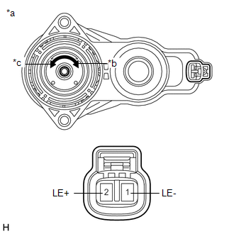
(a) Parking brake actuator assembly LH operation inspection
| (1) Apply voltage to the terminals of the parking brake actuator assembly LH and check that it operates as specified. OK:
If the result is not as specified, replace the parking brake actuator assembly LH. |
|
2. INSPECT PARKING BRAKE ACTUATOR ASSEMBLY RH
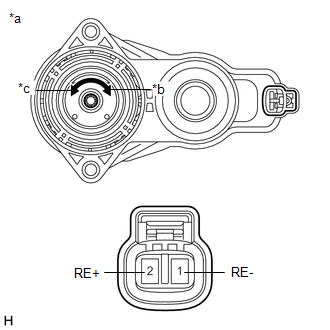
(a) Parking brake actuator assembly RH operation inspection
| (1) Apply voltage to the terminals of the parking brake actuator assembly RH and check that it operates as specified. OK:
If the result is not as specified, replace the parking brake actuator assembly RH. |
|
READ NEXT:
 Installation
INSTALLATION CAUTION / NOTICE / HINT HINT:
Use the same procedure for the RH side and LH side.
The following procedure is for the LH side.
PROCEDURE 1. INSTALL PARKING BRAKE ACTUATOR ASSEMBLY
On-vehicle Inspection
ON-VEHICLE INSPECTION PROCEDURE 1. INSPECT PARKING BRAKE ACTUATOR ASSEMBLY (for Gasoline Model) HINT: Using the GTS to perform the Utilities allows relays, VSVs and actuators and other items to be ope
Removal
REMOVAL CAUTION / NOTICE / HINT HINT:
Use the same procedure for the RH side and LH side.
The following procedure is for the LH side.
PROCEDURE 1. PRECAUTION Click here 2. RELEASE PARKING BR
SEE MORE:
Absorber Control Actuator(for Front Side)
On-vehicle InspectionON-VEHICLE INSPECTION PROCEDURE 1. INSPECT ABSORBER CONTROL ACTUATOR (a) Measure the resistance according to the value(s) in the table below. Standard Resistance: Tester Connection Condition Specified Condition 1 - 2 15 to 25°C 3.3 to 3.7 Ω If the result
Customize Parameters
CUSTOMIZE PARAMETERS CUSTOMIZE SLIDING ROOF SYSTEM HINT: The following items can be customized. NOTICE:
When the customer requests a change in a function, first make sure that the function can be customized.
Be sure to make a note of the current settings before customizing.
When troubleshooti
