Lexus ES: Components
COMPONENTS
ILLUSTRATION
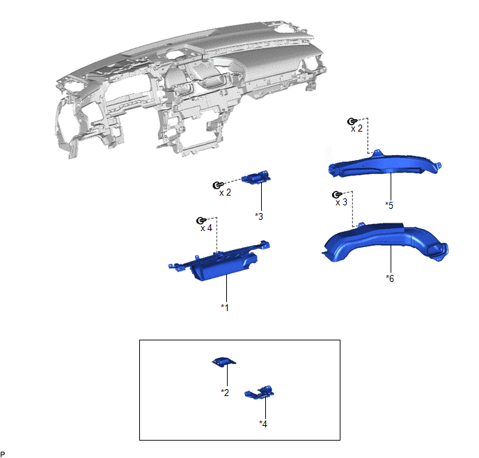
| *1 | DEFROSTER NOZZLE ASSEMBLY | *2 | NAVIGATION ANTENNA ASSEMBLY |
| *3 | NAVIGATION ANTENNA ASSEMBLY WITH BRACKET | *4 | NAVIGATION ANTENNA BRACKET |
| *5 | NO. 2 SIDE DEFROSTER NOZZLE DUCT | *6 | NO. 3 HEATER TO REGISTER DUCT |
READ NEXT:
 Inspection
INSPECTION PROCEDURE 1. INSPECT NAVIGATION ANTENNA ASSEMBLY (w/o Manual (SOS) Switch) (a) Check that the navigation antenna assembly cable is properly installed and does not have any sharp bends, pinc
Installation
INSTALLATION PROCEDURE 1. INSTALL NAVIGATION ANTENNA BRACKET 2. INSTALL NAVIGATION ANTENNA ASSEMBLY (a) Engage the 6 guides and 2 claws to install the navigation antenna assembly as shown in the illus
Removal
REMOVAL CAUTION / NOTICE / HINT The necessary procedures (adjustment, calibration, initialization, or registration) that must be performed after parts are removed and installed, or replaced during nav
SEE MORE:
BSM Buzzer Sound Request Signal Malfunction (C2A5C)
DESCRIPTION This DTC is stored when the rear television camera assembly receives an invalid communication signal from the blind spot monitor sensor RH. DTC No. Detection Item DTC Detection Condition Trouble Area C2A5C BSM Buzzer Sound Request Signal Malfunction An invalid communicat
Diagnostic Trouble Code Chart
DIAGNOSTIC TROUBLE CODE CHART Lane Control System DTC No. Detection Item Link C1A7496 Steering Vibrator Component Internal Failure U010087 Lost Communication with ECM/PCM "A" Missing Message U012587 Lost Communication with Multi-axis Acceleration Sensor Module Miss
© 2016-2026 Copyright www.lexguide.net
