Lexus ES: Installation
INSTALLATION
CAUTION / NOTICE / HINT
NOTICE:
After installing the luggage door hinge torsion bar, use your hand to open and close the luggage door. Make sure the luggage door can open and close smoothly.
PROCEDURE
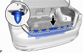
1. INSTALL LUGGAGE COMPARTMENT DOOR TORSION BAR SUPPORT
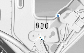
(a) Install a new luggage compartment door torsion bar support as shown in the illustration.
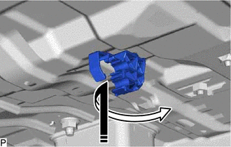
.png) | Install in this Direction |
2. INSTALL LUGGAGE DOOR HINGE TORSION BAR RH
(a) Check the identification mark on the luggage door hinge torsion bar RH.
Identification Mark Color (for TMC Made):
w/o Power Trunk Lid System and Rear Spoiler
No Paint
w/ Power Trunk Lid System
White
w/ Rear Spoiler
Yellow
w/ Power Trunk Lid System and Rear Spoiler
No Paint
Identification Mark Color (for TMMK Made):
w/o Power Trunk Lid System and Rear Spoiler
Gold
w/ Power Trunk Lid System
Light Purple
w/ Rear Spoiler
Light Green
w/ Power Trunk Lid System and Rear Spoiler
Gold
| (b) Insert the tip of the luggage door hinge torsion bar LH in the center installation hole. HINT: The front and rear installation holes are used for adjustment. |
|
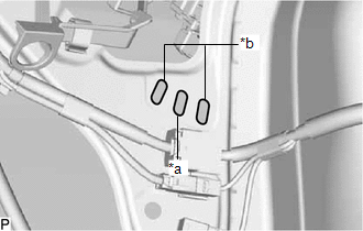
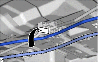
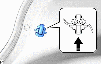
| (c) Engage the 3 guides to connect the luggage door hinge torsion bar RH to the left side of the vehicle body. |
|
.png)
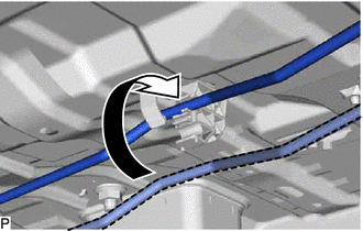
| (d) Connect the luggage door hinge torsion bar RH to the luggage compartment door torsion bar support as shown in the illustration. |
|
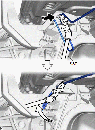
(e) Using SST, install the luggage door hinge torsion bar RH to the luggage door hinge and the right side of the vehicle body as shown in the illustration.
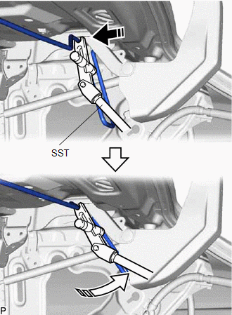
| | Install in this Direction (1) |
.png) | Install in this Direction (2) |
SST: 09804-24010
09804-04010
09804-04020
09804-04030
09804-04040
3. INSTALL LUGGAGE DOOR HINGE TORSION BAR LH
(a) Check the identification mark on the luggage door hinge torsion bar LH.
Identification Mark Color (for TMC Made):
w/o Power Trunk Lid System and Rear Spoiler
No Paint
w/ Power Trunk Lid System
White
w/ Rear Spoiler
Yellow
w/ Power Trunk Lid System and Rear Spoiler
No Paint
Identification Mark Color (for TMMK Made):
w/o Power Trunk Lid System and Rear Spoiler
Red
w/ Power Trunk Lid System
Gray
w/ Rear Spoiler
Dark Blue
w/ Power Trunk Lid System and Rear Spoiler
Red
| (b) Insert the tip of the luggage door hinge torsion bar LH in the center installation hole. HINT: The front and rear installation holes are used for adjustment. |
|
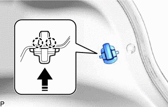
| (c) Engage the 3 guides to connect the luggage door hinge torsion bar LH to the right side of the vehicle body. |
|
.png)
| (d) Connect the luggage door hinge torsion bar LH to the luggage compartment door torsion bar support as shown in the illustration. |
|
(e) Using SST, install the luggage door hinge torsion bar LH to the luggage door hinge and the left side of the vehicle body as shown in the illustration.
| | Install in this Direction (1) |
| | Install in this Direction (2) |
SST: 09804-24010
09804-04010
09804-04020
09804-04030
09804-04040
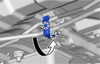
| (f) Engage the 2 claws as shown in the illustration. |
|
4. INSTALL LUGGAGE CLOSER MOTOR ASSEMBLY (w/ Power Trunk Lid System)
Click here .gif)
5. INSTALL LUGGAGE COMPARTMENT DOOR HINGE COVER RH (w/ Power Trunk Lid System)
HINT:
Use the same procedure as for the LH side.
Click here
6. INSTALL LUGGAGE COMPARTMENT DOOR COVER (w/ Power Trunk Lid System)
Click here
7. INSTALL SWITCH BEZEL (w/ Power Trunk Lid System)
Click here
8. INSTALL LUGGAGE LOCK CONTROL CABLE PLATE (w/ Power Trunk Lid System)
Click here
9. INSTALL LUGGAGE COMPARTMENT TRIM INNER COVER LH
(a) Engage the 4 fasteners.
(b) Install the luggage compartment inner trim cover LH with the 4 clips.
(c) Engage the guide.
(d) Install the luggage hold belt striker assembly with the bolt.
(e) Engage the 2 claws to install the rope hook as shown in the illustration.
| | Install in this Direction |
10. INSTALL LUGGAGE COMPARTMENT TRIM INNER COVER RH
(a) Engage each fastener.
(b) Install the luggage compartment inner trim cover RH with the 4 clips.
(c) Engage the guide.
(d) Install the luggage hold belt striker assembly with the bolt.
(e) Engage the 2 claws to install the rope hook as shown in the illustration.
| | Install in this Direction |
11. INSTALL LUGGAGE COMPARTMENT TRIM COVER LH
(a) Engage the 2 claws to install the luggage compartment trim cover LH.
12. INSTALL LUGGAGE COMPARTMENT TRIM COVER RH
(a) Engage the 2 claws to install the luggage compartment trim cover RH.
13. INSTALL REAR FLOOR FINISH PLATE
(a) Engage the 6 clips to install the rear floor finish plate as shown in the illustration.
| | Install in this Direction |
(b) Install the clip.
(c) Engage the guide.
HINT:
Use the same procedure for the RH side and LH side.
(d) Install the luggage hold belt striker assembly with the bolt.
HINT:
Use the same procedure for the RH side and LH side.
14. INSTALL SPARE WHEEL COVER TRAY
(a) Install the spare wheel cover tray.
15. INSTALL LUGGAGE COMPARTMENT FLOOR MAT
(a) Install the luggage compartment floor mat.
16. INITIALIZE POWER TRUNK LID SYSTEM (w/ Power Trunk Lid System)
for Gasoline Model:
Click here
for HV Model:
Click here
17. INSPECT POWER TRUNK LID OPERATION (w/ Power Trunk Lid System)
for Gasoline Model:
Click here
for HV Model:
Click here
READ NEXT:
 Precaution
PRECAUTION PRECAUTIONS FOR INSPECTING POWER SOURCE FOR MAIN BODY ECU (MULTIPLEX NETWORK BODY ECU) NOTICE: When disconnecting the cable from the negative (-) battery terminal, initialize the following
Parts Location
PARTS LOCATION ILLUSTRATION *1 LUGGAGE DOOR OPENING CANCEL SWITCH ASSEMBLY *2 TRUNK AND FUEL SWITCH ASSEMBLY *3 LUGGAGE COMPARTMENT DOOR OPENING SWITCH *4 DLC3 *5 MAIN BODY E
SEE MORE:
Terminals Of Ecu
TERMINALS OF ECU CHECK OUTER MIRROR CONTROL ECU ASSEMBLY (DRIVER DOOR) (a) Disconnect the J28 outer mirror control ECU assembly (driver door) connector. (b) Measure the voltage and resistance according to the value(s) in the table below. HINT: Measure the values on the wire harness side with the co
Components
COMPONENTS ILLUSTRATION *1 NO. 1 ENGINE UNDER COVER *2 FRONT FENDER APRON SEAL LH *3 FRONT FENDER APRON SEAL RH *4 FRONT WHEEL OPENING EXTENSION PAD LH *5 FRONT WHEEL OPENING EXTENSION PAD RH *6 NO. 2 ENGINE UNDER COVER ASSEMBLY N*m (kgf*cm, ft.*lbf): Specified t
