Lexus ES: Parts Location
Lexus ES (XZ10) Service Manual / Vehicle Interior / Door / Hatch / Power Trunk Lid System (for Gasoline Model) / Parts Location
PARTS LOCATION
ILLUSTRATION
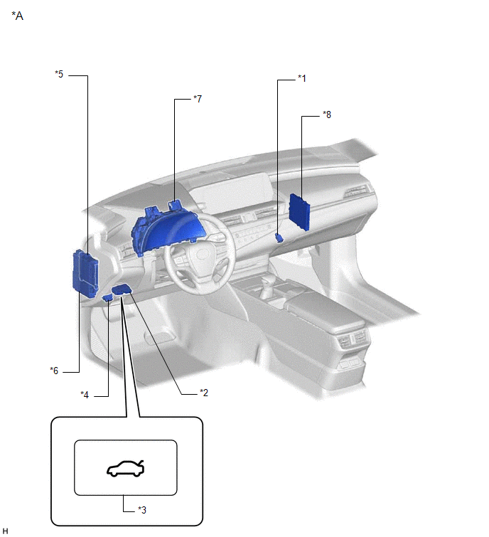
| *1 | LUGGAGE DOOR OPENING CANCEL SWITCH ASSEMBLY | *2 | TRUNK AND FUEL SWITCH ASSEMBLY |
| *3 | LUGGAGE COMPARTMENT DOOR OPENING SWITCH | *4 | DLC3 |
| *5 | MAIN BODY ECU (MULTIPLEX NETWORK BODY ECU) | *6 | INSTRUMENT PANEL JUNCTION BLOCK ASSEMBLY - ECU-DCC NO. 2 FUSE - ECU-IG1 NO. 4 FUSE |
| *7 | COMBINATION METER ASSEMBLY | *8 | CERTIFICATION ECU (SMART KEY ECU ASSEMBLY) |
ILLUSTRATION
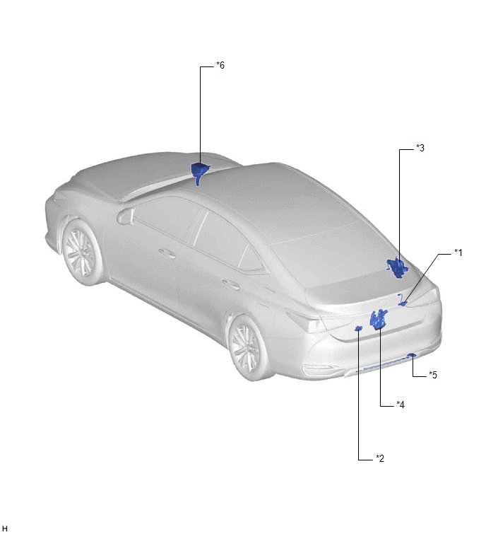
| *1 | LUGGAGE ELECTRICAL KEY SWITCH | *2 | DOOR CONTROL SWITCH |
| *3 | LUGGAGE CLOSER MOTOR ASSEMBLY | *4 | LUGGAGE DOOR CLOSER ASSEMBLY - CLOSER MOTOR - PAWL SWITCH - HALF LATCH SWITCH |
| *5 | KICK DOOR CONTROL SENSOR | *6 | NO. 2 ENGINE ROOM RELAY BLOCK AND NO. 2 JUNCTION BLOCK ASSEMBLY - PTL FUSE |
READ NEXT:
 System Diagram
SYSTEM DIAGRAM Communication Table Transmitting ECU Receiving ECU Signal Communication Method Certification ECU (smart key ECU assembly) Main body ECU (multiplex network body ECU) L
How To Proceed With Troubleshooting
CAUTION / NOTICE / HINT HINT:
Use the following procedure to troubleshoot the power trunk lid system.
*: Use the Techstream.
PROCEDURE 1. VEHICLE BROUGHT TO WORKSHOP
NEXT
Check For Intermittent Problems
CHECK FOR INTERMITTENT PROBLEMS NOTICE:
If the vehicle or vehicle controls are operated (for example, during initial inspection when the vehicle is brought in for repair) before operation history h
SEE MORE:
Cornering Light Circuit
DESCRIPTION The headlight ECU sub-assembly controls the cornering lights. WIRING DIAGRAM except Bulb Type Turn Signal Light (for TMMK Made) for Bulb Type Turn Signal Light (for TMMK Made) CAUTION / NOTICE / HINT NOTICE:
If the headlight ECU sub-assembly LH has been replaced, it is necessary to
System Diagram
SYSTEM DIAGRAM ELECTRICAL REMOTE CONTROL MIRROR FUNCTION MIRROR HEATER FUNCTION AUTOMATIC GLARE-RESISTANT EC MIRROR FUNCTION Communication Table Sender Receiver Signal Communication Method Air Conditioning Control Assembly Air Conditioning Amplifier Assembly Mirror heater switch
© 2016-2026 Copyright www.lexguide.net
