
Lexus ES: Installation
Lexus ES (XZ10) Service Manual / Vehicle Exterior / Wiper / Washer / Washer Level Warning Switch / Installation
INSTALLATION
PROCEDURE
1. INSTALL LEVEL WARNING SWITCH ASSEMBLY
(a) Install the level warning switch assembly as shown in the illustration.
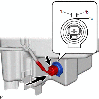
| *a | Protrusion |
| *b | Marking |
.png) | Install in this Direction |
NOTICE:
Make sure that the protrusion of the level warning switch is between the 2 markings.
(b) Connect the connector.
2. ADD WASHER FLUID
Click here .gif)
3. INSTALL FRONT BUMPER ASSEMBLY
Click here
READ NEXT:
 Components
COMPONENTS ILLUSTRATION *1 FRONT FENDER LINER RETAINER *2 FRONT WHEEL OPENING EXTENSION PAD RH *3 PIN HOLD CLIP *4 REAR FENDER SPLASH SHIELD SUB-ASSEMBLY RH *5 WINDSHIELD WAS
Removal
REMOVAL PROCEDURE 1. REMOVE FRONT WHEEL RH Click here 2. REMOVE FRONT WHEEL OPENING EXTENSION PAD RH (a) Remove the 3 screws and front wheel opening extension pad RH. 3. REMOVE REAR F
SEE MORE:
System Diagram
SYSTEM DIAGRAM (a) The CAN communication system is composed of 5 buses. CAN Main Bus Line Terminating Resistor CAN Branch Line * Gateway Function Equipped ECU Bus Monitoring Direction - - Connected to Code ECU/Sensor Name CAN DTC Storage Note - C
Brake Hold Standby Indicator Light Circuit
DESCRIPTION The brake hold standby indicator light turns on if brake hold control is possible when the following conditions required for operation standby are met and the brake hold switch (No. 3 combination switch assembly) is turned on while the power switch is on (IG).
Conditions required for
© 2016-2026 Copyright www.lexguide.net
