Lexus ES: Brake Hold Standby Indicator Light Circuit
DESCRIPTION
The brake hold standby indicator light turns on if brake hold control is possible when the following conditions required for operation standby are met and the brake hold switch (No. 3 combination switch assembly) is turned on while the power switch is on (IG).
-
Conditions required for operation standby:
- The driver side door is closed.
- The driver side seat belt is fastened.
- The system is normal.
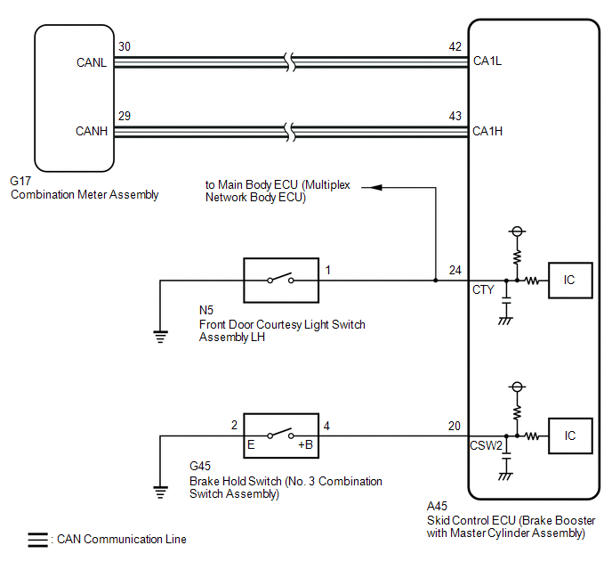
WIRING DIAGRAM
CAUTION / NOTICE / HINT
NOTICE:
After replacing the skid control ECU (brake booster with master cylinder assembly), perform linear solenoid valve offset learning, ABS holding solenoid valve learning, yaw rate and acceleration sensor zero point calibration and system information memorization after performing "Reset Memory".
Click here .gif)
PROCEDURE
| 1. | PRE-CHECK |
(a) If the brake hold standby indicator light does not illuminate even though the brake hold switch (No. 3 combination switch assembly) is pushed, check that the brake hold function operation conditions are met.
- The driver side door is closed.
- The driver side seat belt is fastened.
- The system is normal.
HINT:
If a malfunction occurs in one of the following systems, the brake hold operated indicator light will blink. If this occurs, perform troubleshooting on the malfunctioning system.
- Brake system
- Electric parking brake system
- Hybrid control system
|

| 2. | CHECK CAN COMMUNICATION SYSTEM |
(a) Check if CAN communication system DTCs are output.
Click here
| Result | Proceed to |
|---|---|
| DTCs are not output. | A |
| DTCs are output. | B |
| B |  | INSPECT CAN COMMUNICATION SYSTEM |
|
| 3. | CHECK IF BRAKE BOOSTER WITH MASTER CYLINDER ASSEMBLY CONNECTOR IS SECURELY CONNECTED |
(a) Check if the skid control ECU (brake booster with master cylinder assembly) connector is securely connected.
OK:
The connector is securely connected.
| NG | | CONNECT CONNECTOR TO BRAKE BOOSTER WITH MASTER CYLINDER ASSEMBLY CORRECTLY |
|
| 4. | INSPECT COMBINATION METER ASSEMBLY |
(a) Turn the power switch off.
(b) Perform the Active Test of the combination meter assembly (meter CPU) using the Techstream.
Click here
| Tester Display |
|---|
| Brake Hold Indicator |
(c) Check the combination meter assembly.
OK:
The brake hold standby indicator light turns on or off in accordance with Techstream operation.
| NG | | INSPECT METER / GAUGE SYSTEM |
|
| 5. | PERFORM ACTIVE TEST USING TECHSTREAM (BRAKE HOLD STANDBY INDICATOR LIGHT) |
(a) Select the Active Test on the Techstream.
Click here
| Tester Display | Measurement Item | Control Range | Diagnostic Note |
|---|---|---|---|
| BH Standby Light | Brake hold standby indicator light | Indicator light ON/OFF | Observe combination meter assembly |
| Tester Display | Measurement Item | Range | Normal Condition | Diagnostic Note |
|---|---|---|---|---|
| BH Standby Light | Brake hold standby indicator light | ON or OFF | ON: Indicator light on OFF: Indicator light off | - |
| Active Test Display |
|---|
| BH Standby Light |
| Data List Display |
|---|
| BH Standby Light |
(b) Check the operating condition of the brake hold standby indicator light when operating it using the Techstream.
| Result | Proceed to |
|---|---|
| Brake hold standby indicator light in the Data List does not change using the Active Test. | A |
| Brake hold standby indicator light in the Data List turns ON/OFF using the Active Test. | B |
| A | | REPLACE BRAKE BOOSTER WITH MASTER CYLINDER ASSEMBLY |
|
| 6. | INSPECT NO. 3 COMBINATION SWITCH ASSEMBLY |
| (a) Turn the power switch off. |
|
(b) Make sure that there is no looseness at the locking part and the connecting part of the connector.
OK:
The connector is securely connected.
(c) Disconnect the G45 brake hold switch (No. 3 combination switch assembly) connector.
(d) Check both the connector case and the terminals for deformation and corrosion.
OK:
No deformation or corrosion.
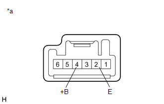
(e) Measure the resistance according to the value(s) in the table below.
Standard Resistance:
| Tester Connection | Condition | Specified Condition |
|---|---|---|
| 4 (+B) - 2 (E) | Switch pushed | Below 1 Ω |
| 4 (+B) - 2 (E) | Switch not pushed | 10 kΩ or higher |
| NG | | REPLACE NO. 3 COMBINATION SWITCH ASSEMBLY |
|
| 7. | CHECK HARNESS AND CONNECTOR (BRAKE BOOSTER WITH MASTER CYLINDER ASSEMBLY - NO. 3 COMBINATION SWITCH ASSEMBLY) |
(a) Make sure that there is no looseness at the locking part and the connecting part of the connector.
OK:
The connector is securely connected.
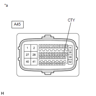
(b) Disconnect the A45 skid control ECU (brake booster with master cylinder assembly) connector.
(c) Check both the connector case and the terminals for deformation and corrosion.
OK:
No deformation or corrosion.
(d) Measure the resistance according to the value(s) in the table below.
Standard Resistance:
| Tester Connection | Condition | Specified Condition |
|---|---|---|
| A45-20 (CSW2) - G45-4 (+B) | Always | Below 1 Ω |
| A45-20 (CSW2) or G45-4 (+B) - Body ground | Always | 10 kΩ or higher |
| G45-2 (E) - Body ground | Always | Below 1 Ω |
| NG | | REPAIR OR REPLACE HARNESS OR CONNECTOR |
|
| 8. | INSPECT FRONT DOOR COURTESY LIGHT SWITCH ASSEMBLY LH |
(a) Turn on the interior lights and check that they illuminate, and then set the switch so that the lights illuminate when the door is opened.
(b) Check that the lights illuminate when the driver side door is opened.
OK:
The interior lights illuminate when the driver side door is opened.
| NG | | INSPECT LIGHTING SYSTEM (COURTESY LIGHT SWITCH CIRCUIT) |
|
| 9. | CHECK HARNESS AND CONNECTOR (CTY TERMINAL) |
| (a) Measure the voltage according to the value(s) in the table below. Standard Voltage:
|
|
| OK | | REPLACE BRAKE BOOSTER WITH MASTER CYLINDER ASSEMBLY |
| NG | | REPAIR OR REPLACE HARNESS OR CONNECTOR (CTY CIRCUIT) |
READ NEXT:
 Brake Warning Light does not Come ON
DESCRIPTION The skid control ECU (brake booster with master cylinder assembly) is connected to the combination meter assembly via CAN communication. CAUTION / NOTICE / HINT NOTICE: After replacing the
Brake Warning Light Remains ON
DESCRIPTION The skid control ECU (brake booster with master cylinder assembly) is connected to the combination meter assembly via CAN communication. If any of the following is detected, the brake warn
EPB System Malfunction (C13AF)
DESCRIPTION The skid control ECU (brake booster with master cylinder assembly) is connected to the parking brake ECU (brake actuator assembly) via CAN communication. If an electric parking brake syste
SEE MORE:
Inspection
INSPECTION PROCEDURE 1. INSPECT FLOW SHUTTING VALVE (WATER BY-PASS HOSE ASSEMBLY) (a) Measure the resistance according to the value(s) in the table below. Standard Resistance: Tester Connection Condition Specified Condition 1 - 2 20°C (68°F) 22 to 28 Ω If the result is not a
Adjustment
ADJUSTMENT CAUTION / NOTICE / HINT *a Centering Bolt *b Standard Bolt HINT:
Use the same procedure for the RH side and LH side.
The following procedure is for the LH side.
Centering bolts are used to install the door hinges to the vehicle body and door. The door cannot be adjus
