Lexus ES: Parts Location
PARTS LOCATION
ILLUSTRATION
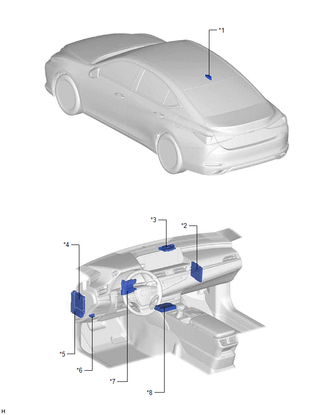
| *1 | ROOF ANTENNA ASSEMBLY - GPS - Telephone Main | *2 | CERTIFICATION ECU (SMART KEY ECU ASSEMBLY) |
| *3 | NAVIGATION ANTENNA ASSEMBLY - Telephone Sub | *4 | MAIN BODY ECU (MULTIPLEX NETWORK BODY ECU) |
| *5 | INSTRUMENT PANEL JUNCTION BLOCK ASSEMBLY - DCM FUSE - ECU-IG2 NO. 3 FUSE | *6 | DLC3 |
| *7 | AIR CONDITIONING AMPLIFIER ASSEMBLY | *8 | DCM (TELEMATICS TRANSCEIVER) |
READ NEXT:
 Precaution
PRECAUTION NOTICE: When disconnecting the cable from the negative (-) battery terminal, initialize the following systems after the terminal is reconnected. System Name See Procedure Lane Cont
Problem Symptoms Table
PROBLEM SYMPTOMS TABLE HINT:
Use the table below to help determine the cause of problem symptoms. If multiple suspected areas are listed, the potential causes of the symptoms are listed in order of
Remote Engine Starter does not Operate
WIRING DIAGRAM CAUTION / NOTICE / HINT NOTICE: Before replacing the DCM (telematics transceiver), refer to Registration. Click here PROCEDURE 1. CHECK SMART KEY SYSTEM (for Start Function)
SEE MORE:
FR Speed Sensor Wrong Installation (X0452)
DESCRIPTION Code Tester Display Measurement Item Trouble Area X0452 FR Speed Sensor Wrong Installation History of front speed sensor RH being installed incorrectly Front Speed Sensor RH PROCEDURE 1. CHECK FOR DTCs (HEALTH CHECK) (a) Perform the Health Check using the T
DCM Data Signal Circuit between Navigation ECU and DCM
DESCRIPTION This circuit is used to send and receive signals between the DCM (Telematics Transceiver), radio receiver assembly and navigation ECU. WIRING DIAGRAM PROCEDURE 1. CHECK HARNESS AND CONNECTOR (RADIO RECEIVER ASSEMBLY - DCM (TELEMATICS TRANSCEIVER)) (a) Disconnect the G128 DCM (T
© 2016-2026 Copyright www.lexguide.net
