Lexus ES: Front Passenger Side Power Mirror cannot be Adjusted with Power Mirror Switch
DESCRIPTION
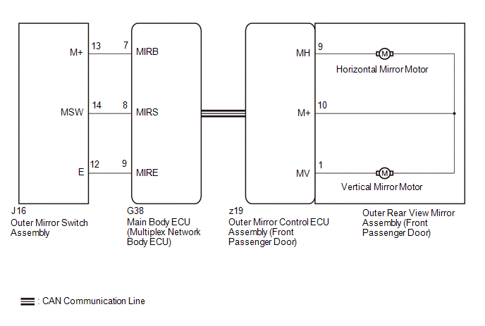
The outer mirror switch assembly sends the mirror adjust switch signals to the main body ECU (multiplex network body ECU). The main body ECU (multiplex network body ECU) then sends the received mirror adjust switch signals to the outer mirror control ECU assembly (front passenger door) via CAN communication. On receiving the signal, the outer mirror control ECU assembly (front passenger door) operates the vertical and horizontal mirror motors, which are built into the outer rear view mirror assembly (front passenger door), to adjust the mirror surface position.
WIRING DIAGRAM
CAUTION / NOTICE / HINT
NOTICE:
-
The power mirror control system (w/ Memory) uses the CAN communication system. Inspect the communication functions by following How to Proceed with Troubleshooting. Troubleshoot the power mirror control system (w/ Memory) after confirming that the communication systems are functioning properly.
Click here
.gif)
-
Before replacing the main body ECU (multiplex network body ECU), refer to Registration.
Click here
PROCEDURE
| 1. | READ VALUE USING TECHSTREAM |
(a) Connect the Techstream to the DLC3.
(b) Turn the engine switch on (IG).
(c) Turn the Techstream on.
(d) Enter the following menus: Body Electrical / Main Body / Data List.
(e) Read the Data List according to the display on the Techstream.
Body Electrical > Main Body > Data List| Tester Display | Measurement Item | Range | Normal Condition | Diagnostic Note |
|---|---|---|---|---|
| Mirror Selection SW (R) | Mirror select switch signal for RH mirror | OFF or ON | OFF: Mirror select switch off ON: Mirror select switch R switch on | - |
| Mirror Selection SW (L) | Mirror select switch signal for LH mirror | OFF or ON | OFF: Mirror select switch off ON: Mirror select switch L switch on | - |
| Mirror Position SW (R) | Mirror adjust switch signal (Right) | OFF or ON | OFF: Mirror adjust switch not pushed right ON: Mirror adjust switch pushed right | Check with the mirror select switch L or R selected |
| Mirror Position SW (L) | Mirror adjust switch signal (Left) | OFF or ON | OFF: Mirror adjust switch not pushed left ON: Mirror adjust switch pushed left | Check with the mirror select switch L or R selected |
| Mirror Position SW (Up) | Mirror adjust switch signal (Up) | OFF or ON | OFF: Mirror adjust switch not pushed up ON: Mirror adjust switch pushed up | Check with the mirror select switch L or R selected |
| Mirror Position SW (Dwn) | Mirror adjust switch signal (Down) | OFF or ON | OFF: Mirror adjust switch not pushed down ON: Mirror adjust switch pushed down | Check with the mirror select switch L or R selected |
| Tester Display |
|---|
| Mirror Selection SW (R) |
| Mirror Selection SW (L) |
| Mirror Position SW (R) |
| Mirror Position SW (L) |
| Mirror Position SW (Up) |
| Mirror Position SW (Dwn) |
OK:
On the Techstream screen, ON or OFF is displayed accordingly.
| NG | .gif) | GO TO STEP 3 |
|
.gif)
| 2. | INSPECT OUTER REAR VIEW MIRROR ASSEMBLY (FRONT PASSENGER DOOR) (MIRROR SURFACE) |
(a) Remove the outer rear view mirror assembly (front passenger door).
Click here
(b) Inspect the outer rear view mirror assembly (front passenger door) (mirror surface).
Click here
| OK | | REPLACE OUTER MIRROR CONTROL ECU ASSEMBLY RH |
| NG | | REPLACE OUTER REAR VIEW MIRROR ASSEMBLY RH |
| 3. | INSPECT OUTER MIRROR SWITCH ASSEMBLY |
(a) Remove the outer mirror switch assembly.
Click here
(b) Inspect the outer mirror switch assembly.
Click here
| NG | | REPLACE OUTER MIRROR SWITCH ASSEMBLY |
|
| 4. | CHECK HARNESS AND CONNECTOR (OUTER MIRROR SWITCH ASSEMBLY - MAIN BODY ECU (MULTIPLEX NETWORK BODY ECU)) |
(a) Disconnect the G38 main body ECU (multiplex network body ECU).
(b) Measure the resistance according to the value(s) in the table below.
Standard Resistance:
| Tester Connection | Condition | Specified Condition |
|---|---|---|
| J16-12 (E) - G38-9 (MIRE) | Always | Below 1 Ω |
| J16-13 (M+) - G38-7 (MIRB) | Always | Below 1 Ω |
| J16-14 (MSW) - G38-8 (MIRS) | Always | Below 1 Ω |
| J16-12 (E) or G38-9 (MIRE) - Body ground | Always | 10 kΩ or higher |
| J16-13 (M+) or G38-7 (MIRB) - Body ground | Always | 10 kΩ or higher |
| J16-14 (MSW) or G38-8 (MIRS) - Body ground | Always | 10 kΩ or higher |
| OK | | REPLACE MAIN BODY ECU (MULTIPLEX NETWORK BODY ECU) |
| NG | | REPAIR OR REPLACE HARNESS OR CONNECTOR |
READ NEXT:
 Power Mirror cannot be Adjusted with Power Mirror Switch
DESCRIPTION The outer mirror switch assembly sends the mirror adjust switch signals to the main body ECU (multiplex network body ECU). The main body ECU (multiplex network body ECU) then sends the rec
Mirror Heater does not Operate with Rear Defogger Switch
DESCRIPTION When the mirror heater switch (rear window defogger switch) is operated, the mirror heater signal is sent to the air conditioning amplifier assembly and then to each outer mirror control E
Power Retractable Mirrors do not Operate with Power Retract Mirror Switch
DESCRIPTION The outer mirror switch assembly sends the retractable outer mirror switch signal to the main body ECU (multiplex network body ECU). The main body ECU (multiplex network body ECU) then sen
SEE MORE:
Transmission Range Sensor "A" Circuit (PRNDL Input) Signal Compare Failure (P070562)
DESCRIPTION The shift lever position sensor sends 7 different switch signals to the hybrid vehicle control ECU. The hybrid vehicle control ECU uses these signals to detect the shift lever position (P, R, N or D). The hybrid vehicle control ECU also uses this information to determine the intended dir
Dtc Check / Clear
DTC CHECK / CLEAR CHECK DTC (a) Connect the Techstream to the DLC3. (b) Turn the engine switch on (IG). (c) Turn the Techstream on. (d) Enter the following menus: Chassis > Front Recognition Camera > Trouble Codes (e) Check for DTCs (Test Failed / Pending / Confirmed). Techstream Display
