Lexus ES: Installation
INSTALLATION
PROCEDURE
1. INSTALL REAR ENGINE OIL SEAL
(a) Using height adjustment attachments and plate lift attachments, place the engine assembly on a flat level surface.
NOTICE:
- Using height adjustment attachments and plate lift attachments, keep the engine assembly level.
- To prevent the No. 2 oil pan sub-assembly from deforming, do not place any attachments under the No. 2 oil pan sub-assembly of the engine assembly.
- Using an engine sling device and engine lift, secure the engine assembly before servicing.
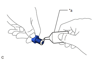
| (b) Apply MP grease to the lip of a new rear engine oil seal. NOTICE:
|
|
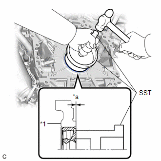
(c) Using SST and a hammer, tap in the rear engine oil seal.
SST: 09223-15030
SST: 09950-70010
09951-07150
Oil Seal Protrusion Height:
-0.5 to 0.5 mm (-0.0197 to 0.0197 in.)
NOTICE:
Do not tap in the rear engine oil seal at an angle.
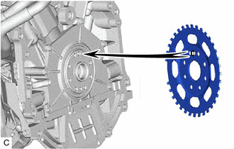
2. INSTALL NO. 1 CRANKSHAFT POSITION SENSOR PLATE
| (a) Install the No. 1 crankshaft position sensor plate. HINT: Align the pin of the No. 1 crankshaft position sensor plate with the pin hole of the crankshaft. |
|
3. INSTALL DRIVE PLATE AND RING GEAR SUB-ASSEMBLY
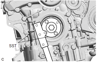
| (a) Using SST, hold the crankshaft pulley. SST: 09213-70011 09213-70020 SST: 09330-00021 |
|
(b) Clean the 8 bolts and 8 bolt holes.
(c) Install the drive plate and ring gear sub-assembly and rear drive plate spacer to the crankshaft.
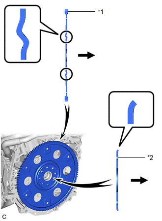
| *1 | Drive Plate and Ring Gear Sub-assembly |
| *2 | Rear Drive Plate Spacer |
.png) | Transaxle Side |
| (d) Apply adhesive to 2 or 3 threads at the end of each of the 8 bolts. Adhesive: Toyota Genuine Adhesive 1324, Three Bond 1324 or equivalent |
|
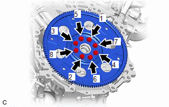
| (e) Install and uniformly tighten the 8 bolts in several steps in the sequence shown in the illustration. Torque: 83 N·m {846 kgf·cm, 61 ft·lbf} NOTICE: Do not start the engine for at least 1 hour after installing the drive plate and ring gear sub-assembly. |
|
4. INSTALL AUTOMATIC TRANSAXLE ASSEMBLY
Click here .gif)
READ NEXT:
 Components
COMPONENTS ILLUSTRATION *1 FUEL SUCTION PLATE SUB-ASSEMBLY *2 NO. 1 FUEL SUCTION SUPPORT *3 FUEL FILTER - -
SEE MORE:
Initialization
INITIALIZATION NOTICE:
The necessary procedures (adjustment, calibration, initialization or registration) that must be performed after parts are removed and installed, or replaced during headlight ECU sub-assembly LH removal/installation are shown below. for LED Type Turn Signal Light Replaced
Starter Signal Circuit
DESCRIPTION While the engine is being cranked, current flows from terminal STAR of the certification ECU (smart key ECU assembly) to the park/neutral position switch assembly and to terminal STA of the ECM (STA signal). WIRING DIAGRAM Refer to DTC P061512. Click here CAUTION / NOTICE / HINT NOTIC
