Lexus ES: Lost Communication with Front Shade Module (B2346)
DESCRIPTION
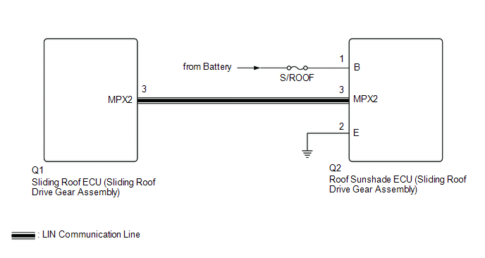
This DTC is stored when LIN communication between the sliding roof ECU (sliding roof drive gear assembly) and roof sunshade ECU (sliding roof drive gear assembly) stops for 10 seconds or more.
| DTC No. | Detection Item | DTC Detection Condition | Trouble Area |
|---|---|---|---|
| B2346 | Lost Communication with Front Shade Module | No communication between the sliding roof ECU (sliding roof drive gear assembly) and roof sunshade ECU (sliding roof drive gear assembly) for 10 seconds or more. |
|
WIRING DIAGRAM
CAUTION / NOTICE / HINT
NOTICE:
- Inspect the fuses for circuits related to this system before performing the following inspection procedure.
-
When the sliding roof ECU (sliding roof drive gear assembly) is removed and reinstalled or replaced, the sliding roof ECU (sliding roof drive gear assembly) must be initialized.
Click here
.gif)
-
When the roof sunshade ECU (sliding roof drive gear assembly) is removed and reinstalled or replaced, the roof sunshade ECU (sliding roof drive gear assembly) must be initialized.
Click here
PROCEDURE
| 1. | CHECK FOR DTC |
(a) Clear the DTCs.
Body Electrical > Sliding Roof > Clear DTCs(b) Check for DTCs.
Body Electrical > Sliding Roof > Trouble CodesOK:
DTC B2346 is not output.
| NG | .gif) | USE SIMULATION METHOD TO CHECK |
|
.gif)
| 2. | CHECK HARNESS AND CONNECTOR (SLIDING ROOF ECU (SLIDING ROOF DRIVE GEAR ASSEMBLY) - ROOF SUNSHADE ECU (SLIDING ROOF DRIVE GEAR ASSEMBLY)) |
(a) Disconnect the Q1 sliding roof ECU (sliding roof drive gear assembly) connector.
(b) Disconnect the Q2 roof sunshade ECU (sliding roof drive gear assembly) connector.
(c) Measure the resistance according to the value(s) in the table below.
Standard Resistance:
| Tester Connection | Condition | Specified Condition |
|---|---|---|
| Q1-3 (MPX2) - Q2-3 (MPX2) | Always | Below 1 Ω |
| Q1-3 (MPX2) - Body ground | Always | 10 kΩ or higher |
| NG | | REPAIR OR REPLACE HARNESS OR CONNECTOR |
|
| 3. | CHECK HARNESS AND CONNECTOR (FRONT ROOF SUNSHADE ECU (SLIDING ROOF DRIVE GEAR ASSEMBLY) - BATTERY AND BODY GROUND) |
(a) Disconnect the Q2 roof sunshade ECU (sliding roof drive gear assembly) connector.
(b) Measure the resistance according to the value(s) in the table below.
Standard Resistance:
| Tester Connection | Condition | Specified Condition |
|---|---|---|
| Q2-2 (E) - Body ground | Always | Below 1 Ω |
(c) Measure the voltage according to the value(s) in the table below.
Standard Voltage:
| Tester Connection | Condition | Specified Condition |
|---|---|---|
| Q2-1 (B) - Body ground | Always | 11 to 14 V |
| NG | | REPAIR OR REPLACE HARNESS OR CONNECTOR |
|
| 4. | CHECK ROOF SUNSHADE ECU (SLIDING ROOF DRIVE GEAR ASSEMBLY) |
(a) Temporarily replace the roof sunshade ECU (sliding roof drive gear assembly) with a new or normally functioning one.
Click here
|
| 5. | CHECK FOR DTC |
(a) Clear the DTCs.
Body Electrical > Sliding Roof > Clear DTCs(b) Check for DTCs.
Body Electrical > Sliding Roof > Trouble CodesOK:
DTC B2346 is not output.
| OK | | END (ROOF SUNSHADE ECU (SLIDING ROOF DRIVE GEAR ASSEMBLY) IS DEFECTIVE) |
| NG | | REPLACE SLIDING ROOF ECU (SLIDING ROOF DRIVE GEAR ASSEMBLY) |
READ NEXT:
 Sensor (Motor) Failure (Fr Shade) (B2347,B2349)
DESCRIPTION When the roof sunshade ECU (sliding roof drive gear assembly) detects a motor malfunction and the sliding roof operation is stopped, DTC B2347 is stored. When the roof sunshade ECU (slidin
Position Initialization Incomplete (Fr Shade) (B2348)
DESCRIPTION This DTC is stored when the roof sunshade ECU (sliding roof drive gear assembly) has not been initialized. DTC No. Detection Item DTC Detection Condition Trouble Area B2348
Motor Control Relay Stuck ON (Fr Shade) (B234A)
DESCRIPTION This DTC will be stored if the operation of the front roof sunshade is suspended and a pulse input of 10 Hz or more is detected when the motor relay is off. DTC No. Detection Item D
SEE MORE:
Parts Location
PARTS LOCATION ILLUSTRATION *1 DEICER RELAY *2 NO. 2 ENGINE ROOM RELAY BLOCK AND NO. 2 ENGINE ROOM JUNCTION BLOCK ASSEMBLY - DEICER FUSE *3 MULTI-DISPLAY ASSEMBLY - FRONT WIPER DEICER SWITCH *4 WINDSHIELD DEICER WIRE (WINDSHIELD GLASS) *5 DLC3 *6 AIR CONDITIONING AMPLIF
EPB Switch Malfunction (C13B4)
DESCRIPTION When the electric parking brake switch is pushed, a lock request signal is sent from the parking brake ECU (brake actuator assembly) to the parking brake actuator assembly. When the electric parking brake switch is pulled, a release request signal is sent from the parking brake ECU (brak
