
Lexus ES: Installation
INSTALLATION
PROCEDURE
1. INSTALL REAR BUMPER ASSEMBLY
(a) w/ Wire Harness:
(1) Connect the connector.
(b) Engage the 6 claws as shown in the illustration.
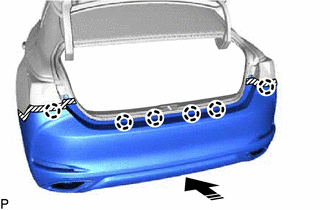
.png) | Install in this Direction |
(c) Engage the 6 claws as shown in the illustration.
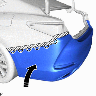
| | Install in this Direction |
HINT:
Use the same procedure for the RH side and LH side.
(d) Install the 12 clips.
(e) Install the screw.
HINT:
Use the same procedure for the RH side and LH side.
(f) Engage the 2 claws.
HINT:
Use the same procedure for the RH side and LH side.
(g) Install the clip.
HINT:
Use the same procedure for the RH side and LH side.
(h) Install the rear bumper assembly with the 2 screws.
2. INSTALL REAR COMBINATION LIGHT COVER LH
Click here .gif)
3. INSTALL REAR COMBINATION LIGHT COVER RH
HINT:
Use the same procedure as for the LH side.
4. CONNECT CABLE TO NEGATIVE BATTERY TERMINAL (w/ Hands Free Power Trunk Lid)
for 2GR-FKS:
Click here
for A25A-FKS:
Click here
5. INITIALIZE KICK DOOR CONTROL SENSOR (w/ Hands Free Power Trunk Lid)
Click here
6. INSPECT KICK DOOR CONTROL SENSOR (w/ Hands Free Power Trunk Lid)
Click here
7. PERFORM CALIBRATION (w/ Parking Support Brake System)
Click here
READ NEXT:
 Components
COMPONENTS ILLUSTRATION *1 REAR BUMPER ASSEMBLY *2 REAR COMBINATION LIGHT COVER LH *3 REAR COMBINATION LIGHT COVER RH - - ILLUSTRATION *A w/ Hands Free Power Trunk Lid -
Removal
REMOVAL CAUTION / NOTICE / HINT The necessary procedures (adjustment, calibration, initialization, or registration) that must be performed after parts are removed and installed, or replaced during rea
SEE MORE:
Rear Power Window RH does not Operate with Rear Power Window Switch RH
DESCRIPTION When the engine switch is on (IG), the power window regulator motor assembly (for rear RH door) is operated by the rear power window regulator switch assembly (for RH door). The power window regulator motor assembly (for rear RH door) has motor, regulator, and ECU functions. WIRING DIAGR
Fail-safe Chart
FAIL-SAFE CHART If the following DTC is stored, the ECM enters fail-safe mode to allow the vehicle to be driven temporarily. DTC No. Fail-safe Operation Fail-safe Deactivation Condition P161A87 Generator command is fixed. Engine switch is turned on (IG) after condition returns to norm
