Lexus ES: Components
COMPONENTS
ILLUSTRATION
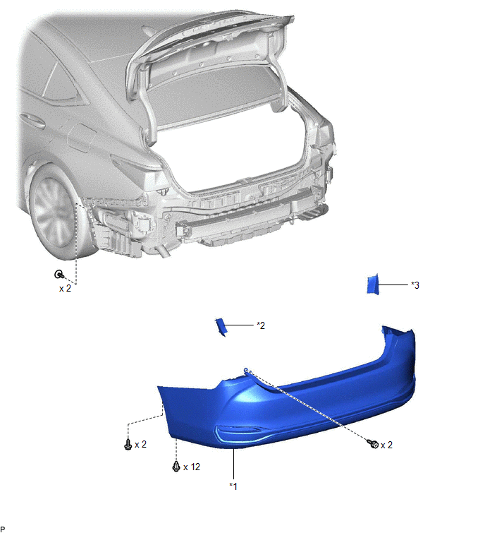
| *1 | REAR BUMPER ASSEMBLY | *2 | REAR COMBINATION LIGHT COVER LH |
| *3 | REAR COMBINATION LIGHT COVER RH | - | - |
ILLUSTRATION
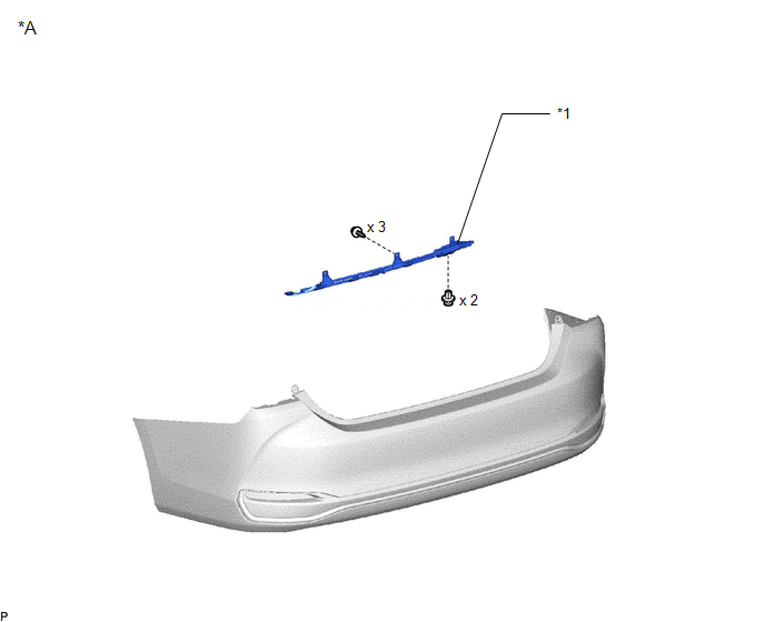
| *A | w/ Hands Free Power Trunk Lid | - | - |
| *1 | KICK DOOR CONTROL SENSOR WITH BRACKET | - | - |
ILLUSTRATION
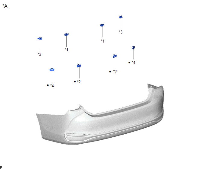
| *A | w/ Parking Support Alert System | - | - |
| *1 | REAR CENTER ULTRASONIC SENSOR | *2 | REAR CENTER ULTRASONIC SENSOR RETAINER |
| *3 | REAR CORNER ULTRASONIC SENSOR | *4 | REAR CORNER ULTRASONIC SENSOR RETAINER |
| ● | Non-reusable part | - | - |
ILLUSTRATION
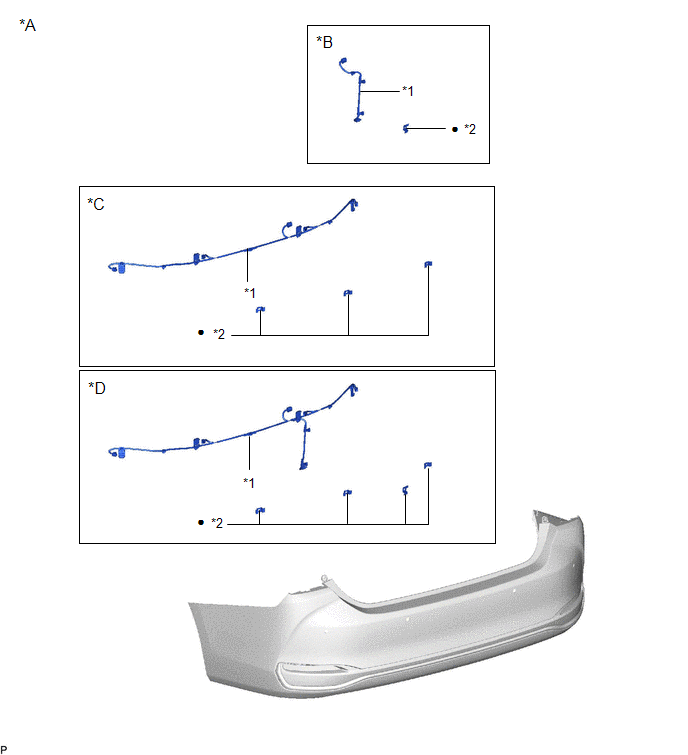
| *A | w/ Wire Harness | *B | w/ Hands Free Power Trunk Lid without Parking Support Alert System |
| *C | w/ Parking Support Alert System without Hands Free Power Trunk Lid | *D | w/ Hands Free Power Trunk Lid and Parking Support Alert System |
| *1 | NO. 2 LUGGAGE ROOM WIRE | *2 | ULTRASONIC SENSOR CLIP |
| ● | Non-reusable part | - | - |
ILLUSTRATION
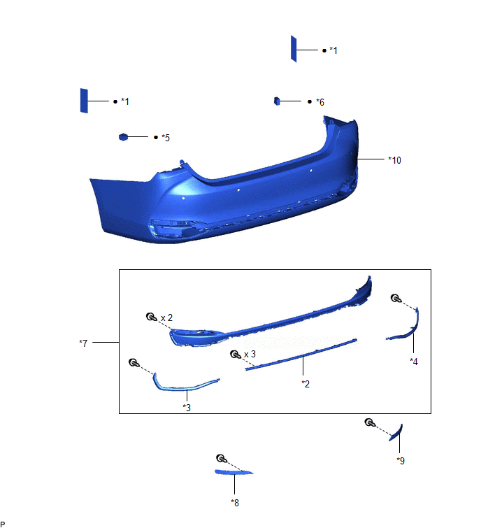
| *1 | NO. 1 MOULDING TAPE | *2 | REAR BUMPER BAR |
| *3 | REAR BUMPER BAR LH | *4 | REAR BUMPER BAR RH |
| *5 | REAR BUMPER PAD LH | *6 | REAR BUMPER PAD RH |
| *7 | REAR CENTER BUMPER SUB-ASSEMBLY | *8 | REFLEX REFLECTOR ASSEMBLY LH |
| *9 | REFLEX REFLECTOR ASSEMBLY RH | *10 | REAR BUMPER COVER |
| ● | Non-reusable part | - | - |
ILLUSTRATION
.png)
| *1 | LUGGAGE COMPARTMENT FLOOR MAT | *2 | SPARE WHEEL COVER TRAY |
ILLUSTRATION
.png)
| *1 | REAR FLOOR FINISH PLATE | *2 | LUGGAGE HOLD BELT STRIKER ASSEMBLY |
ILLUSTRATION
.png)
| *A | w/o Power Trunk Lid System | *B | w/ Power Trunk Lid System |
| *C | for Type A | *D | for Type B |
| *1 | LUGGAGE COMPARTMENT TRIM COVER LH | *2 | LUGGAGE COMPARTMENT TRIM COVER RH |
| *3 | LUGGAGE COMPARTMENT TRIM INNER COVER LH | *4 | LUGGAGE COMPARTMENT TRIM INNER COVER RH |
| *5 | ROPE HOOK | *6 | LUGGAGE HOLD BELT STRIKER ASSEMBLY |
ILLUSTRATION
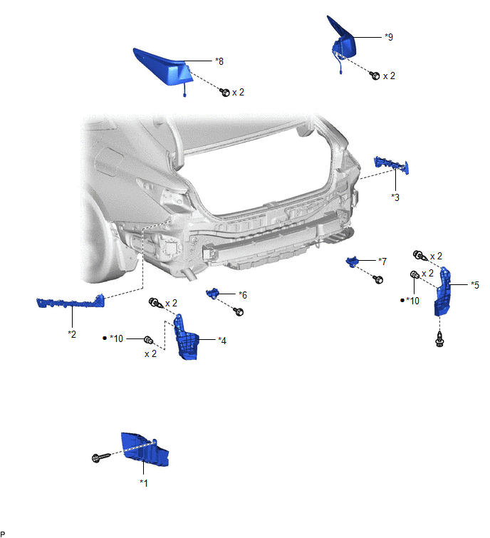
| *1 | LOWER REAR BUMPER SIDE RETAINER LH | *2 | NO. 2 REAR BUMPER SIDE SUPPORT LH |
| *3 | NO. 2 REAR BUMPER SIDE SUPPORT RH | *4 | REAR BUMPER SIDE SUPPORT LH |
| *5 | REAR BUMPER SIDE SUPPORT RH | *6 | REAR BUMPER UPPER RETAINER LH |
| *7 | REAR BUMPER UPPER RETAINER RH | *8 | REAR COMBINATION LIGHT LENS AND BODY LH |
| *9 | REAR COMBINATION LIGHT LENS AND BODY RH | *10 | GROMMET |
| ● | Non-reusable part | - | - |
ILLUSTRATION
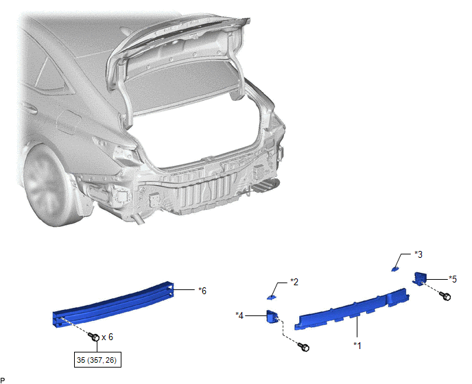
| *1 | REAR BUMPER ENERGY ABSORBER | *2 | REAR BUMPER PROTECTOR INSERT LH |
| *3 | REAR BUMPER PROTECTOR INSERT RH | *4 | REAR BUMPER PROTECTOR LH |
| *5 | REAR BUMPER PROTECTOR RH | *6 | REAR BUMPER REINFORCEMENT |
.png) | N*m (kgf*cm, ft.*lbf): Specified torque | - | - |
READ NEXT:
 Removal
REMOVAL CAUTION / NOTICE / HINT The necessary procedures (adjustment, calibration, initialization, or registration) that must be performed after parts are removed and installed, or replaced during rea
Disassembly
DISASSEMBLY PROCEDURE 1. REMOVE KICK DOOR CONTROL SENSOR WITH BRACKET (w/ Hands Free Power Trunk Lid) Click here 2. REMOVE REAR CENTER ULTRASONIC SENSOR (w/ Parking Support Alert System) Click her
Reassembly
REASSEMBLY PROCEDURE 1. INSTALL REAR BUMPER REINFORCEMENT (a) Install the rear bumper reinforcement with the 6 bolts. Torque: 35 N·m {357 kgf·cm, 26 ft·lbf} 2. INSTALL REAR BUMPER P
SEE MORE:
Check Bus 2 Line for Short to GND
DESCRIPTION There may be a short circuit between one of the CAN bus lines and GND when there is no resistance between terminal 18 (CA4H) of the central gateway ECU (network gateway ECU) and terminal 4 (CG) of the DLC3, or terminal 17 (CA4L) of the central gateway ECU (network gateway ECU) and termin
ABS Malfunction (C1296)
DESCRIPTION If a malfunction in the speed sensor signal circuit or yaw rate and acceleration sensor (airbag ECU assembly) circuit occurs, the 4WD ECU assembly will output this DTC. The airbag ECU assembly has a built-in yaw rate and acceleration sensor. DTC No. Detection Item DTC Detection Co
