Lexus ES: Purge Valve
Components
COMPONENTS
ILLUSTRATION
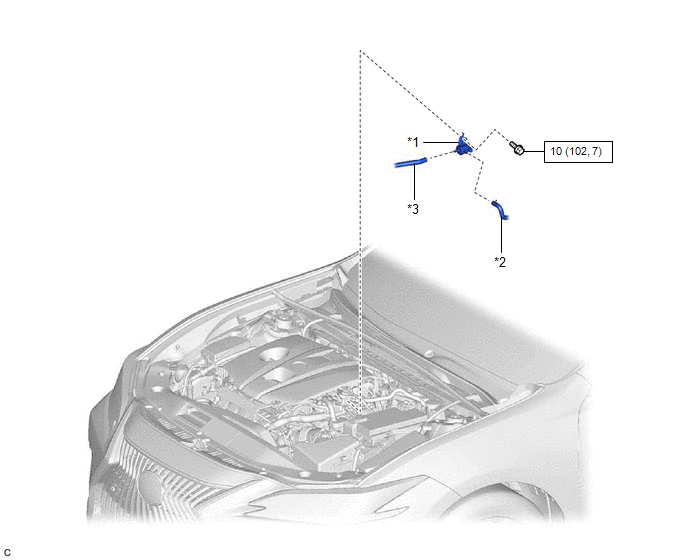
| *1 | PURGE VALVE (PURGE VSV) | *2 | NO. 1 FUEL VAPOR FEED HOSE |
| *3 | NO. 2 FUEL VAPOR FEED HOSE | - | - |
.png) | N*m (kgf*cm, ft.*lbf): Specified torque | - | - |
Removal
REMOVAL
PROCEDURE
1. REMOVE PURGE VALVE (PURGE VSV)
| (a) Disconnect the purge valve (purge VSV) connector. |
|
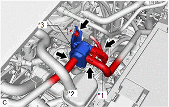
(b) Slide the clip and disconnect the No. 1 fuel vapor feed hose from the purge valve (purge VSV).
(c) Disconnect the No. 2 fuel vapor feed hose from the purge valve (purge VSV).
(d) Remove the bolt and purge valve (purge VSV) from the purge VSV bracket.
Inspection
INSPECTION
PROCEDURE
1. INSPECT PURGE VALVE (PURGE VSV)
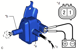
(a) Measure the resistance according to the value(s) in the table below.
Standard Resistance:
| Tester Connection | Condition | Specified Condition |
|---|---|---|
| 1 - 2 | 20°C (68°F) | 23 to 26 Ω |
If the result is not as specified, replace the purge valve (purge VSV).
| (b) Apply battery voltage between the terminals of the purge valve (purge VSV) and check that the following occurs when blowing air into the port (E). OK:
If the result is not as specified, replace the purge valve (purge VSV). |
|
Installation
INSTALLATION
PROCEDURE
1. INSTALL PURGE VALVE (PURGE VSV)
| (a) Install the purge valve (purge VSV) to the purge VSV bracket with the bolt. Torque: 10 N·m {102 kgf·cm, 7 ft·lbf} |
|
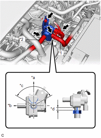
(b) Connect the No. 2 fuel vapor feed hose to the purge valve (purge VSV).
(c) Connect the No. 1 fuel vapor feed hose to the purge valve (purge VSV) and slide the clip to secure it.
HINT:
Engage the clip within the area shown in the illustration.
(d) Connect the purge valve (purge VSV) connector.
READ NEXT:
 Vacuum Sensor
ComponentsCOMPONENTS ILLUSTRATION *1 E.F.I. VACUUM SENSOR ASSEMBLY (MANIFOLD ABSOLUTE PRESSURE SENSOR) *2 VACUUM HOSE N*m (kgf*cm, ft.*lbf): Specified torque - - RemovalREMOV
SEE MORE:
Diagnostic Trouble Code Chart
DIAGNOSTIC TROUBLE CODE CHART Power Steering System DTC No. Detection Item DTC Detection Condition Warning Indicate Return-to-normal Condition Note Link C1511 Torque Sensor1 Torque sensor malfunction EPS warning light: Comes on Power switch is turned on (IG) again -
Motor/Generator Shutdown Signal (Hybrid/EV Side) Stuck Off (P33B99F)
DTC SUMMARY MALFUNCTION DESCRIPTION The hybrid vehicle control ECU detects malfunctions which prevent the inverter with converter assembly emergency shutdown circuit (HSDN) from shutting down the hybrid control system. Detection is performed when the power switch is turned on (IG) and during the shu
