Lexus ES: Installation
INSTALLATION
CAUTION / NOTICE / HINT
HINT:
- Use the same procedure for the RH side and LH side.
- The following procedure is for the LH side.
PROCEDURE
1. PRECAUTION
NOTICE:
After turning the engine switch (for Gasoline Model) or power switch (for HV Model) off, waiting time may be required before disconnecting the cable from the negative (-) auxiliary battery terminal. Therefore, make sure to read the disconnecting the cable from the negative (-) auxiliary battery terminal notices before proceeding with work.
Click here .gif)
2. INSTALL FRONT DOOR BELT MOULDING ASSEMBLY
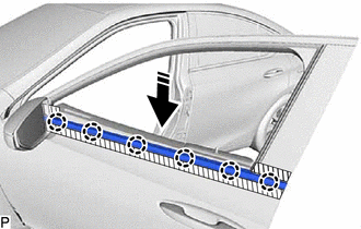
.png) | Install in this Direction |
(a) Engage the 6 claws to install a new front door belt moulding assembly as shown in the illustration.
3. INSTALL FRONT DOOR GLASS SUB-ASSEMBLY
Click here
4. INSTALL FRONT DOOR PANEL PROTECTOR
Click here
5. INSTALL FRONT DOOR VENT SEAL
Click here
6. INSTALL FRONT DOOR SERVICE HOLE COVER
Click here
7. INSTALL FRONT DOOR TRIM BRACKET
Click here
8. INSTALL FRONT DOOR LOWER FRAME BRACKET GARNISH
Click here
9. INSTALL FRONT DOOR TRIM BOARD SUB-ASSEMBLY
Click here
10. INSTALL COURTESY LIGHT ASSEMBLY
Click here
11. INSTALL MULTIPLEX NETWORK MASTER SWITCH ASSEMBLY WITH FRONT DOOR UPPER ARMREST BASE PANEL (for Driver Side)
Click here
12. INSTALL POWER WINDOW REGULATOR SWITCH ASSEMBLY WITH FRONT DOOR UPPER ARMREST BASE PANEL (for Front Passenger Side)
Click here
13. INSTALL NO. 2 DOOR TRIM PAD
Click here
14. CONNECT CABLE TO NEGATIVE AUXILIARY BATTERY TERMINAL
for 2GR-FKS:
Click here
for A25A-FXS:
Click here
for A25A-FKS:
Click here
15. INITIALIZE POWER WINDOW CONTROL SYSTEM
for HV Model:
Click here
for Gasoline Model:
Click here
16. INSPECT POWER WINDOW OPERATION
for HV Model:
Click here
for Gasoline Model:
Click here
READ NEXT:
 Components
COMPONENTS ILLUSTRATION *1 FRONT DOOR FRONT LOWER FRAME UPPER COVER *2 FRONT DOOR GLASS RUN *3 FRONT DOOR OUTSIDE MOULDING SUB-ASSEMBLY *4 FRONT DOOR REAR WINDOW FRAME MOULDING
Removal
REMOVAL CAUTION / NOTICE / HINT The necessary procedures (adjustment, calibration, initialization, or registration) that must be performed after parts are removed and installed, or replaced during fro
SEE MORE:
Voice is not Recognized
PROCEDURE 1. CHECK CONDITION (a) While paying attention to the condition of the spoken voice command, perform a voice recognition operation. OK: Voice command is recognized normally. HINT:
When the voice command is recognized, the content of the voice command is displayed in the voice r
Vacuum Sensor
ComponentsCOMPONENTS ILLUSTRATION *1 E.F.I. VACUUM SENSOR ASSEMBLY (MANIFOLD ABSOLUTE PRESSURE SENSOR) *2 VACUUM HOSE N*m (kgf*cm, ft.*lbf): Specified torque - - RemovalREMOVAL CAUTION / NOTICE / HINT NOTICE: This procedure includes the removal of small-head bolts. Refer to
