Lexus ES: Vacuum Sensor
Components
COMPONENTS
ILLUSTRATION
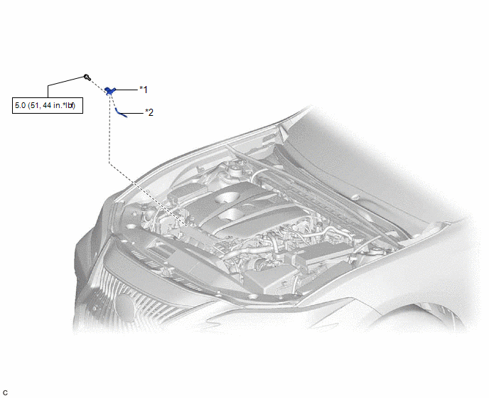
| *1 | E.F.I. VACUUM SENSOR ASSEMBLY (MANIFOLD ABSOLUTE PRESSURE SENSOR) | *2 | VACUUM HOSE |
.png) | N*m (kgf*cm, ft.*lbf): Specified torque | - | - |
Removal
REMOVAL
CAUTION / NOTICE / HINT
NOTICE:
This procedure includes the removal of small-head bolts. Refer to Small-Head Bolts of Basic Repair Hint to identify the small-head bolts.
Click here .gif)
PROCEDURE
1. REMOVE E.F.I. VACUUM SENSOR ASSEMBLY (MANIFOLD ABSOLUTE PRESSURE SENSOR)
| (a) Disconnect the E.F.I. vacuum sensor assembly (manifold absolute pressure sensor) connector. |
|
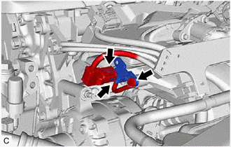
(b) Disconnect the vacuum hose from the E.F.I. vacuum sensor assembly (manifold absolute pressure sensor).
(c) Using an 8 mm socket wrench, remove the bolt and E.F.I. vacuum sensor assembly (manifold absolute pressure sensor) from the intake manifold.
Installation
INSTALLATION
CAUTION / NOTICE / HINT
NOTICE:
This procedure includes the installation of small-head bolts. Refer to Small-Head Bolts of Basic Repair Hint to identify the small-head bolts.
Click here .gif)
PROCEDURE
1. INSTALL E.F.I. VACUUM SENSOR ASSEMBLY (MANIFOLD ABSOLUTE PRESSURE SENSOR)
(a) Using an 8 mm socket wrench, install the E.F.I. vacuum sensor assembly (manifold absolute pressure sensor) to the intake manifold with the bolt.
Torque:
5.0 N·m {51 kgf·cm, 44 in·lbf}
(b) Connect the vacuum hose to the E.F.I. vacuum sensor assembly (manifold absolute pressure sensor).
(c) Connect the E.F.I. vacuum sensor assembly (manifold absolute pressure sensor) connector.
READ NEXT:
 Components
COMPONENTS ILLUSTRATION *1 ACCELERATOR PEDAL ASSEMBLY *2 ACCELERATOR PEDAL PAD *3 ACCELERATOR PEDAL SENSOR ASSEMBLY *4 NO. 1 INSTRUMENT PANEL UNDER COVER SUB-ASSEMBLY Tighte
SEE MORE:
Headlight Swivel ECU LH Communication (B2410,B2411)
DESCRIPTION Each headlight ECU sub-assembly and headlight swivel motor communicate via LIN communication. The headlight swivel motor operates according to power supplied and automatic headlight beam level control signals from its respective headlight ECU sub-assembly and sends its operating state to
Components
COMPONENTS ILLUSTRATION *1 AIR CLEANER CAP WITH AIR CLEANER HOSE *2 COOL AIR INTAKE DUCT SEAL *3 INLET AIR CLEANER ASSEMBLY *4 NO. 1 ENGINE COVER SUB-ASSEMBLY *5 THROTTLE BODY GASKET *6 THROTTLE BODY WITH MOTOR ASSEMBLY *7 NO. 2 VENTILATION HOSE *8 NO. 6 WATER
