Lexus ES: Removal
REMOVAL
CAUTION / NOTICE / HINT
The necessary procedures (adjustment, calibration, initialization, or registration) that must be performed after parts are removed and installed, or replaced during front door window frame moulding removal/installation are shown below.
Necessary Procedure After Parts Removed/Installed/Replaced (for HV Model)| Replaced Part or Performed Procedure | Necessary Procedure | Effect/Inoperative Function When Necessary Procedures are not Performed | Link |
|---|---|---|---|
|
*: When performing learning using the Techstream.
Click here | |||
| Disconnect cable from negative auxiliary battery terminal | Perform steering sensor zero point calibration | Lane Control System | |
| Pre-collision System | |||
| Parking Support Brake System* | |||
| Lighting System | |||
| Memorize steering angle neutral point | Parking Assist Monitor System | | |
| Panoramic View Monitor System | | ||
| Initialize power trunk lid system | Power Trunk Lid System | | |
| Initialize power window control system |
| |
NOTICE:
- After the power switch is turned off, the radio receiver assembly records various types of memory and settings. As a result, after turning the power switch off, make sure to wait at least 85 seconds before disconnecting the cable from the negative (-) auxiliary battery terminal. (for Audio and Visual System)
- After the power switch is turned off, the radio receiver assembly records various types of memory and settings. As a result, after turning the power switch off, make sure to wait at least 85 seconds before disconnecting the cable from the negative (-) auxiliary battery terminal. (for Navigation System)
| Replaced Part or Performed Procedure | Necessary Procedure | Effect/Inoperative Function When Necessary Procedures are not Performed | Link |
|---|---|---|---|
|
*: When performing learning using the Techstream.
Click here | |||
| Disconnect cable from negative battery terminal | Perform steering sensor zero point calibration | Lane Control System | |
| Pre-collision System | |||
| Parking Support Brake System* | |||
| Lighting System | |||
| Memorize steering angle neutral point | Parking Assist Monitor System | | |
| Panoramic View Monitor System | | ||
| Initialize power trunk lid system | Power Trunk Lid System | | |
| Initialize power window control system |
| |
NOTICE:
- After the engine switch is turned off, the radio receiver assembly records various types of memory and settings. As a result, after turning the engine switch off, make sure to wait at least 85 seconds before disconnecting the cable from the negative (-) battery terminal. (for Audio and Visual System)
- After the engine switch is turned off, the radio receiver assembly records various types of memory and settings. As a result, after turning the engine switch off, make sure to wait at least 85 seconds before disconnecting the cable from the negative (-) battery terminal. (for Navigation System)
HINT:
- Use the same procedure for the RH side and LH side.
- The following procedure is for the LH side.
PROCEDURE
1. REMOVE FRONT DOOR BELT MOULDING ASSEMBLY
Click here .gif)
2. REMOVE FRONT DOOR FRONT LOWER FRAME UPPER COVER
Click here
3. REMOVE FRONT DOOR GLASS RUN
Click here
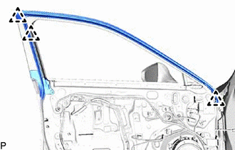
4. DISCONNECT FRONT DOOR WEATHERSTRIP
| (a) Disengage the 3 clips and disconnect the front door weatherstrip. |
|
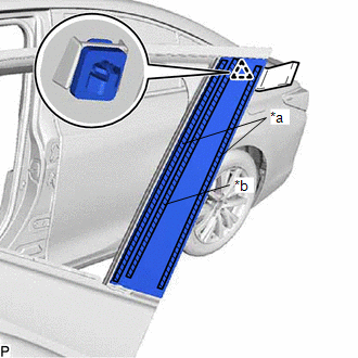
5. REMOVE FRONT DOOR REAR WINDOW FRAME MOULDING
HINT:
When removing the front door rear window frame moulding, heat the vehicle body and front door rear window frame moulding using a heat light.
Heating Temperature| Item | Temperature |
|---|---|
| Vehicle Body | 40 to 60°C (104 to 140°F) |
| Front Door Rear Window Frame Moulding | 20 to 30°C (68 to 86°F) |
CAUTION:
- Do not touch the heat light and heated parts, touching the heat light may result in burns.
- Touching heated parts for a long time may result in burns.
.png)
| *a | Heated Part |
| *b | Heat Light |
NOTICE:
Do not heat the vehicle body or front door rear window frame moulding excessively.
(a) Using a heat light, heat the front door rear window frame moulding.
| (b) Using a moulding remover, disengage the clip and separate the double-sided tape and caulking sponge to remove the front door rear window frame moulding. |
|
6. REMOVE FRONT DOOR OUTSIDE MOULDING SUB-ASSEMBLY
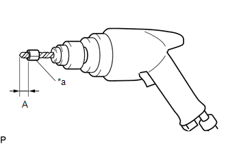
(a) Insert a 4.0 mm (0.157 in.) drill bit into a drill.
| (b) Tape the 4.0 mm (0.157 in.) drill bit 5.0 mm (0.197 in.) from the tip as shown in the illustration. Standard Measurement:
NOTICE: Tape the 4.0 mm (0.157 in.) drill bit to prevent the drill bit from going too deep. |
|
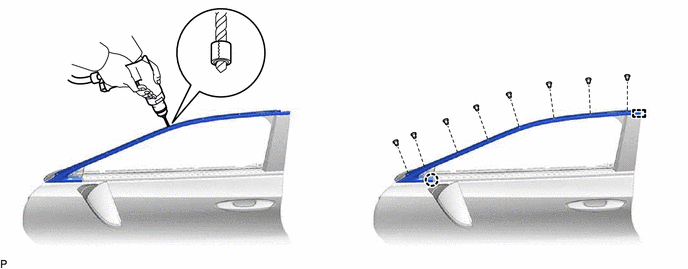
(c) Lightly press the drill bit against the rivets to drill off the rivet flanges, and remove the 8 rivets.
CAUTION:
Be careful of the drilled rivets, as they may be hot.
NOTICE:
- Pressing the drill too firmly will cause the rivet to turn and result in the rivet not being drilled through.
- Prying the rivets with the drill may damage the rivet installation holes or drill bit.
(d) Using a vacuum cleaner, remove the rivet fragments and shavings from the drilled areas.
(e) Disengage the claw and guide to remove the front door outside moulding sub-assembly from the door frame.
READ NEXT:
 Installation
INSTALLATION CAUTION / NOTICE / HINT HINT:
Use the same procedure for the RH side and LH side.
The following procedure is for the LH side.
PROCEDURE 1. INSTALL FRONT DOOR OUTSIDE MOULDING SUB-
Components
COMPONENTS ILLUSTRATION *A for Driver Side *B for Front Passenger Side *1 COURTESY LIGHT ASSEMBLY *2 FRONT DOOR TRIM BOARD SUB-ASSEMBLY *3 MULTIPLEX NETWORK MASTER SWITCH ASS
SEE MORE:
NTSC Disconnected (from Park Assist/Monitoring ECU) (B1535,C1622)
DESCRIPTION These DTCs are stored if the radio receiver assembly judges that the signals or signal lines between the rear television camera assembly and the multi-display assembly are not normal as a result of its self check. DTC No. Detection Item DTC Detection Condition Trouble Area B
Freeze Frame Data
FREEZE FRAME DATA CHECK FREEZE FRAME DATA HINT: Whenever an active noise control system DTC is stored, the stereo component equalizer assembly stores the current vehicle state as freeze frame data. (a) Connect the Techstream to the DLC3. (b) Turn the engine switch on (IG). (c) Turn the Techstream on
