Lexus ES: Installation
INSTALLATION
PROCEDURE
1. INSTALL DECK SIDE TRIM COVER RH
(a) Engage the clip to install the deck side trim cover RH.
2. INSTALL LUGGAGE CLOSER MOTOR ASSEMBLY
(a) Connect the connector.
(b) Engage the 2 clamps.
(c) Engage the 2 guides.
| (d) Install the luggage closer motor assembly with the 3 bolts. HINT: Tighten the bolts in the order shown in the illustration. Torque: 5.5 N·m {56 kgf·cm, 49 in·lbf} |
|
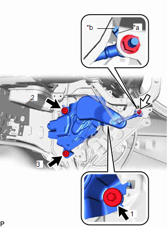
(e) Align the protrusion of the power luggage door rod sub-assembly with the edge of luggage compartment door hinge assembly RH and connect the power luggage door rod sub-assembly as shown in the illustration.
(f) Install the nut.
Torque:
5.5 N·m {56 kgf·cm, 49 in·lbf}
3. INSTALL LUGGAGE COMPARTMENT TRIM INNER COVER RH
Click here .gif)
4. INSTALL LUGGAGE COMPARTMENT TRIM COVER RH
Click here
5. INSTALL LUGGAGE COMPARTMENT DOOR HINGE COVER RH
HINT:
Use the same procedure as for the LH side.
Click here
6. INSTALL LUGGAGE COMPARTMENT DOOR COVER
Click here
7. INSTALL SWITCH BEZEL
Click here
8. INSTALL LUGGAGE LOCK CONTROL CABLE PLATE
Click here
9. INSTALL REAR FLOOR FINISH PLATE
Click here
10. INSTALL SPARE WHEEL COVER TRAY
Click here
11. INSTALL LUGGAGE COMPARTMENT FLOOR MAT
Click here
12. INITIALIZE POWER TRUNK LID SYSTEM
for Gasoline Model:
Click here
for HV Model:
Click here
13. INSPECT POWER TRUNK LID OPERATION
for Gasoline Model:
Click here
for HV Model:
Click here
READ NEXT:
 Components
COMPONENTS ILLUSTRATION *A for Driver Side *B for Front Passenger Side *1 COURTESY LIGHT ASSEMBLY *2 FRONT DOOR TRIM BOARD SUB-ASSEMBLY *3 MULTIPLEX NETWORK MASTER SWITCH ASS
SEE MORE:
Components
COMPONENTS ILLUSTRATION *1 STEERING WHEEL ASSEMBLY - - Tightening torque for "Major areas involving basic vehicle performance such as moving/turning/stopping": N*m (kgf*cm, ft.*lbf) - - ILLUSTRATION *1 HEATED STEERING WHEEL CONTROLLER (STEERING VIBRATION ECU) *2 STE
Hybrid Transaxle System
On-vehicle InspectionON-VEHICLE INSPECTION CAUTION / NOTICE / HINT CAUTION: To prevent injury due to contact with an operating V-ribbed belt or cooling fan, keep your hands and clothing away from the V-ribbed belt and cooling fans when working in the engine compartment with the engine running or th
