Lexus ES: Components
COMPONENTS
ILLUSTRATION
.png)
| *1 | STEERING WHEEL ASSEMBLY | - | - |
.png) | Tightening torque for "Major areas involving basic vehicle performance such as moving/turning/stopping": N*m (kgf*cm, ft.*lbf) | - | - |
ILLUSTRATION
.png)
| *1 | HEATED STEERING WHEEL CONTROLLER (STEERING VIBRATION ECU) | *2 | STEERING WHEEL PAD BRACKET |
ILLUSTRATION
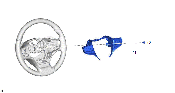
| *1 | STEERING PAD SWITCH ASSEMBLY | - | - |
ILLUSTRATION
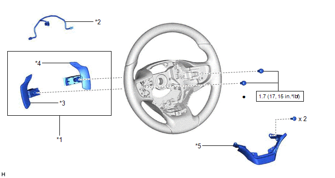
| *1 | SHIFT PADDLE SWITCH (TRANSMISSION SHIFT SWITCH ASSEMBLY) | *2 | NO. 1 SWITCH WIRE |
| *3 | SHIFT PADDLE SWITCH LH (TRANSMISSION SHIFT SWITCH ASSEMBLY) | *4 | SHIFT PADDLE SWITCH RH (TRANSMISSION SHIFT SWITCH ASSEMBLY) |
| *5 | NO. 1 STEERING WHEEL ORNAMENT | - | - |
.png) | N*m (kgf*cm, ft.*lbf): Specified torque | ● | Non-reusable part |
| ★ | Precoated part | - | - |
READ NEXT:
 Removal
REMOVAL CAUTION / NOTICE / HINT The necessary procedures (adjustment, calibration, initialization or registration) that must be performed after parts are removed and installed, or replaced during stee
Installation
INSTALLATION CAUTION / NOTICE / HINT NOTICE:
Do not remove/install the spiral cable with sensor sub-assembly with the auxiliary battery connected and the engine switch (for Gasoline Model) or power
Installation
INSTALLATION CAUTION / NOTICE / HINT NOTICE:
Do not remove/install the spiral cable with sensor sub-assembly with the auxiliary battery connected and the engine switch (for Gasoline Model) or power
SEE MORE:
Removal
REMOVAL CAUTION / NOTICE / HINT The necessary procedures (adjustment, calibration, initialization, or registration) that must be performed after parts are removed and installed, or replaced during telephone and GPS antenna assembly removal/installation are shown below. Necessary Procedure After Part
Data List / Active Test
DATA LIST / ACTIVE TEST DATA LIST NOTICE: In the table below, the values listed under "Normal Condition" are reference values. Do not depend solely on these reference values when deciding whether a part is faulty or not. (a) Connect the Techstream to the DLC3. (b) Turn the engine switch on (IG). (c)
© 2016-2026 Copyright www.lexguide.net
