Lexus ES: Components
Lexus ES (XZ10) Service Manual / Vehicle Exterior / Lighting (ext) / Headlight Dimmer Switch / Components
COMPONENTS
ILLUSTRATION
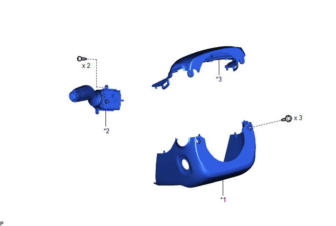
| *1 | LOWER STEERING COLUMN COVER SUB-ASSEMBLY | *2 | TURN SIGNAL SWITCH |
| *3 | UPPER STEERING COLUMN COVER | - | - |
READ NEXT:
 Removal
REMOVAL PROCEDURE 1. CHANGE POWER TILT AND POWER TELESCOPIC STEERING COLUMN SYSTEM SETTINGS (for Power Tilt and Power Telescopic Steering Column) Click here 2. REMOVE LOWER STEERING COLUMN COVER S
Inspection
INSPECTION PROCEDURE 1. INSPECT TURN SIGNAL SWITCH (a) Measure the resistance according to the value(s) in the table below. Standard Resistance: Light Control Switch Tester Connection Conditi
Installation
INSTALLATION PROCEDURE 1. INSTALL TURN SIGNAL SWITCH (a) Engage the claw as shown in the illustration. Install in this Direction (b) Install the turn signal switch with the 2 screws. 2. INST
SEE MORE:
Automatic Light Control Sensor
ComponentsCOMPONENTS ILLUSTRATION *1 AUTOMATIC LIGHT CONTROL SENSOR *2 NO. 1 SPEAKER OPENING COVER ASSEMBLY On-vehicle InspectionON-VEHICLE INSPECTION PROCEDURE 1. INSPECT AUTOMATIC LIGHT CONTROL SENSOR (a) Disconnect the H3 automatic light control sensor connector. *a
Data List / Active Test
DATA LIST / ACTIVE TEST DATA LIST HINT: Using the Techstream to read the Data List allows the values or states of switches, sensors, actuators and other items to be read without removing any parts. This non-intrusive inspection can be very useful because intermittent conditions or signals may be dis
© 2016-2026 Copyright www.lexguide.net
