Lexus ES: Installation
INSTALLATION
PROCEDURE
1. ALIGN FRONT WHEELS FACING STRAIGHT AHEAD
2. INSTALL STEERING COLUMN ASSEMBLY
NOTICE:
Make sure that the wire harness is not interfering with the steering column assembly.
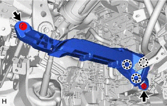
(a) Install the steering column assembly with the bolt and 2 nuts.
Torque:
36 N·m {367 kgf·cm, 27 ft·lbf}
NOTICE:
- After the column is installed, check the tilt operation.
-
If a large amount of force is required to operate the tilt mechanism or abnormal noise occurs, loosen the nuts and move the bracket forward or backward until the tilt operation works smoothly.
Tighten the nuts and check the tilt operation again.
(b) Connect each connector and engage each wire harness clamp to the steering column assembly.
3. INSTALL STEERING INTERMEDIATE SHAFT ASSEMBLY
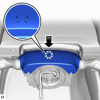
(a) Align the matchmarks on the steering intermediate shaft assembly and steering column assembly.
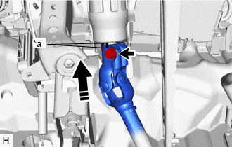
| *a | Matchmark |
.png) | Install in this direction |
(b) Install the steering intermediate shaft assembly to the steering column assembly.
(c) Install the bolt.
Torque:
35 N·m {357 kgf·cm, 26 ft·lbf}
| (d) Tighten the clamp. |
|
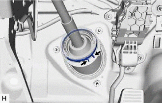
4. INSTALL STEERING COLUMN HOLE COVER
(a) Install the steering column hole cover with the 2 clips.
(b) Install the clip.
(c) Return the floor carpet.
5. CONNECT STEERING INTERMEDIATE SHAFT ASSEMBLY
Click here .gif)
6. INSTALL FRONT WHEEL LH
Click here
7. INSTALL NO. 1 AIR DUCT SUB-ASSEMBLY
| (a) Engage the 3 claws to install a new No. 1 air duct sub-assembly. |
|
(b) Install the 2 bolts.
Torque:
9.8 N·m {100 kgf·cm, 87 in·lbf}
8. INSTALL LOWER NO. 1 INSTRUMENT PANEL AIRBAG ASSEMBLY
Click here
9. INSTALL TURN SIGNAL SWITCH ASSEMBLY WITH SPIRAL CABLE SUB-ASSEMBLY
NOTICE:
- Do not remove/install the spiral cable with sensor sub-assembly with the auxiliary battery connected and the engine switch (for Gasoline Model) or power switch (for HV Model) on (IG).
- Do not rotate the spiral cable with sensor sub-assembly without the steering wheel assembly installed, with the auxiliary battery connected and the engine switch (for Gasoline Model) or power switch (for HV Model) on (IG).
- Ensure that the steering wheel assembly is installed and aligned straight when inspecting the steering sensor.
| (a) Using pliers, expand the clamp. |
|
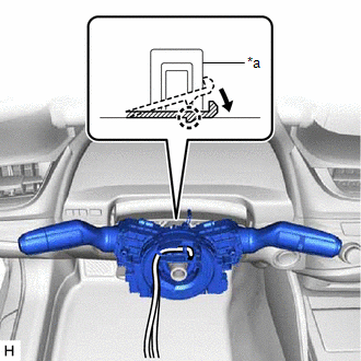
(b) While holding the clamp expanded, install the turn signal switch assembly with spiral cable sub-assembly to the steering column assembly and engage the claw.
(c) Return the clamp to its original position.
(d) Connect the connectors to the turn signal switch assembly with spiral cable sub-assembly.
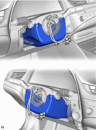
10. INSTALL UPPER STEERING COLUMN COVER
| (a) Engage the 2 claws and 4 clips to connect the upper steering column cover. |
|
.png)
(b) Engage the claw to install the upper steering column cover.
| | Install in this direction |
11. INSTALL LOWER STEERING COLUMN COVER SUB-ASSEMBLY
| (a) Engage the 2 claws to install the lower steering column cover sub-assembly. |
|
| (b) Install the 3 screws. |
|
.png)
12. ALIGN FRONT WHEELS FACING STRAIGHT AHEAD
13. INSPECT AND ADJUST SPIRAL CABLE WITH SENSOR SUB-ASSEMBLY
Click here
14. INSTALL STEERING WHEEL ASSEMBLY
Click here
15. CHECK STEERING WHEEL CENTER POINT
16. INSTALL HORN BUTTON ASSEMBLY
Click here
17. PERFORM INITIALIZATION AND CALIBRATION (for Gasoline Model)
for Parking Assist Monitor System Initialization: Click here
for Parking Assist Monitor System Calibration: Click here
for Panoramic View Monitor System Initialization: Click here
for Panoramic View Monitor System Calibration: Click here
for Parking Support Brake System Calibration: Click here
18. PERFORM INITIALIZATION AND CALIBRATION (for HV Model)
for Parking Assist Monitor System Initialization: Click here
for Parking Assist Monitor System Calibration: Click here
for Panoramic View Monitor System Initialization: Click here
for Panoramic View Monitor System Calibration: Click here
for Parking Support Brake System Calibration: Click here
19. PERFORM REGISTRATION (for Gasoline Model)
Click here
20. PERFORM REGISTRATION (for HV Model)
Click here
READ NEXT:
 Components
COMPONENTS ILLUSTRATION *1 STEERING WHEEL ASSEMBLY - - Tightening torque for "Major areas involving basic vehicle performance such as moving/turning/stopping": N*m (kgf*cm, ft.*lbf)
Removal
REMOVAL CAUTION / NOTICE / HINT The necessary procedures (adjustment, calibration, initialization or registration) that must be performed after parts are removed and installed, or replaced during stee
SEE MORE:
Customize Parameters
CUSTOMIZE PARAMETERS CUSTOMIZE HEATED STEERING WHEEL SYSTEM (a) Customizing with the Techstream. NOTICE:
When the customer requests a change in a function, first make sure that the function can be customized.
Be sure to make a note of the current settings before customizing.
When troubleshoot
Hybrid/EV Battery Positive Contactor Circuit Stuck Closed (P0AA000)
DTC SUMMARY MALFUNCTION DESCRIPTION The hybrid vehicle control ECU detects a stuck closed malfunction of a system main relay on the HV battery positive (+) terminal side. The cause of this malfunction may be one of the following: Inverter voltage sensor (VH) internal circuit malfunction
Voltage s
