Lexus ES: Installation
INSTALLATION
CAUTION / NOTICE / HINT
NOTICE:
This procedure includes the installation of small-head bolts. Refer to Small-Head Bolts of Basic Repair Hint to identify the small-head bolts.
Click here .gif)
PROCEDURE
1. TEMPORARILY INSTALL FUEL (ENGINE ROOM SIDE) PUMP ASSEMBLY
NOTICE:
When replacing the fuel pump assembly, it is necessary to replace the No. 1 fuel pipe sub-assembly with a new one.
HINT:
Perform "Inspection After Repair" after replacing the fuel pump assembly.
Click here
| (a) Turn the crankshaft pulley until the flat of the No. 2 camshaft faces the fuel pump lifter assembly. HINT: This prevents the No. 2 camshaft nose from pushing up the fuel pump lifter assembly when installing the fuel pump assembly. |
|
| (b) Apply 30 cc (1.8 cu. in.) of engine oil to the pump drive cam. |
|
(c) Apply engine oil to the fuel pump lifter assembly.
(d) Install a new fuel pump spacer gasket to the cylinder head cover sub-assembly.
| (e) Apply engine oil to the inside of the fuel pump lifter guide and the outside of the fuel pump lifter assembly. |
|
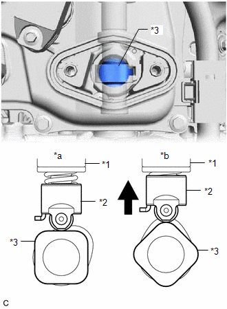
(f) Set the fuel pump lifter assembly on the fuel pump lifter guide as shown in the illustration.
HINT:
Align the stopper key of the fuel pump lifter assembly with the key groove of the fuel pump lifter guide.
(g) Apply engine oil to a new O-ring and install it to the fuel pump assembly.
NOTICE:
Do not damage the O-ring.
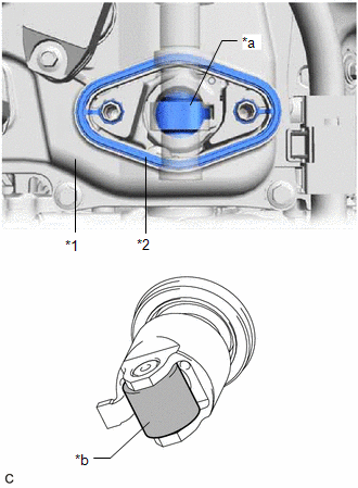
| (h) Set the fuel pump flange and fuel pump assembly on the cylinder head cover sub-assembly as shown in the illustration. |
|
(i) Temporarily install the fuel pump assembly with the 2 bolts, leaving some allowance for left and right movement.
2. TEMPORARILY INSTALL NO. 1 FUEL PIPE SUB-ASSEMBLY
NOTICE:
Do not damage the seals of the union nuts of the No. 1 fuel pipe sub-assembly.
(a) Temporarily install the bolt.
(b) Temporarily install the No. 1 fuel pipe sub-assembly to the fuel delivery pipe and tighten the union nut by hand.
(c) Temporarily install the No. 1 fuel pipe sub-assembly to the fuel pump assembly and tighten the union nut by hand.
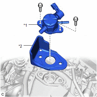
3. INSTALL FUEL (ENGINE ROOM SIDE) PUMP ASSEMBLY
(a) Tighten the 2 bolts.
Torque:
28.5 N·m {291 kgf·cm, 21 ft·lbf}
(b) Connect the fuel pump assembly connector.
4. INSTALL NO. 1 FUEL PIPE SUB-ASSEMBLY
(a) for EGR Valve Bracket Connection Type:
(1) Using a 17 mm union nut wrench, tighten the union nut on the fuel delivery pipe side of the No. 1 fuel pipe sub-assembly.
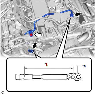
| *a | 17 mm Union Nut Wrench |
| *b | Torque Wrench Fulcrum Length |
.png) | Union Nut |
.png) | Bolt |
Torque:
Specified tightening torque :
35 N·m {357 kgf·cm, 26 ft·lbf}
NOTICE:
Do not adjust the torque in the loosening direction.
HINT:
-
Calculate the torque wrench reading when changing the fulcrum length of the torque wrench.
Click here
- When using a 17 mm union nut wrench (fulcrum length of 30 mm (1.18 in.)) + torque wrench (fulcrum length of 180 mm (7.09 in.)): 30 N*m (306 kgf*cm, 22 ft.*lbf)
(2) Using a 17 mm union nut wrench, tighten the union nut on the fuel pump assembly side of the No. 1 fuel pipe sub-assembly.
Torque:
Specified tightening torque :
35 N·m {357 kgf·cm, 26 ft·lbf}
NOTICE:
Do not adjust the torque in the loosening direction.
HINT:
-
Calculate the torque wrench reading when changing the fulcrum length of the torque wrench.
Click here
- When using a 17 mm union nut wrench (fulcrum length of 30 mm (1.18 in.)) + torque wrench (fulcrum length of 180 mm (7.09 in.)): 30 N*m (306 kgf*cm, 22 ft.*lbf)
(3) Using an 8 mm socket wrench, tighten the bolt.
Torque:
10 N·m {102 kgf·cm, 7 ft·lbf}
(b) for Cylinder Head Cover Sub-assembly Connection Type:
(1) Using a 17 mm union nut wrench, tighten the union nut on the fuel delivery pipe side of the No. 1 fuel pipe sub-assembly.
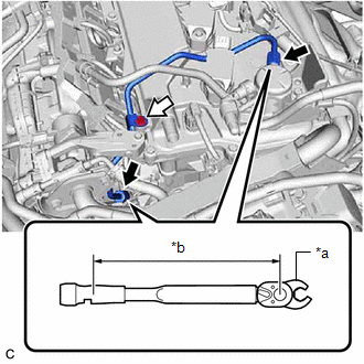
| *a | 17 mm Union Nut Wrench |
| *b | Torque Wrench Fulcrum Length |
| | Union Nut |
| | Bolt |
Torque:
Specified tightening torque :
35 N·m {357 kgf·cm, 26 ft·lbf}
NOTICE:
Do not adjust the torque in the loosening direction.
HINT:
-
Calculate the torque wrench reading when changing the fulcrum length of the torque wrench.
Click here
- When using a 17 mm union nut wrench (fulcrum length of 30 mm (1.18 in.)) + torque wrench (fulcrum length of 180 mm (7.09 in.)): 30 N*m (306 kgf*cm, 22 ft.*lbf)
(2) Using a 17 mm union nut wrench, tighten the union nut on the fuel pump assembly side of the No. 1 fuel pipe sub-assembly.
Torque:
Specified tightening torque :
35 N·m {357 kgf·cm, 26 ft·lbf}
NOTICE:
Do not adjust the torque in the loosening direction.
HINT:
-
Calculate the torque wrench reading when changing the fulcrum length of the torque wrench.
Click here
- When using a 17 mm union nut wrench (fulcrum length of 30 mm (1.18 in.)) + torque wrench (fulcrum length of 180 mm (7.09 in.)): 30 N*m (306 kgf*cm, 22 ft.*lbf)
(3) Using an 8 mm socket wrench, tighten the bolt.
Torque:
10 N·m {102 kgf·cm, 7 ft·lbf}
(c) Connect the ignition coil connector.
5. INSTALL NO. 2 WATER BY-PASS PIPE
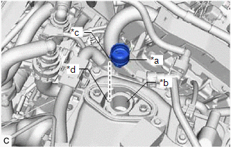
| (a) Temporarily install the No. 2 water by-pass pipe to the cylinder block sub-assembly with the bolt (B). |
|
.png)
(b) Using an 8 mm socket wrench, temporarily install the No. 2 water by-pass pipe to the intake manifold with the 2 bolts (A).
(c) Tighten the bolt (B).
Torque:
21 N·m {214 kgf·cm, 15 ft·lbf}
(d) Using the 8 mm socket wrench, tighten the 2 bolts (A).
Torque:
10 N·m {102 kgf·cm, 7 ft·lbf}
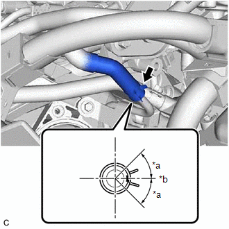
| (e) Connect the No. 8 water by-pass hose to the No. 2 water by-pass pipe and slide the clip to secure it. HINT: Engage the clip within the area shown in the illustration. |
|
(f) Engage the clamp to connect the HV air conditioning wire.
6. CONNECT FUEL TUBE SUB-ASSEMBLY
(a) Connect the fuel tube sub-assembly to the fuel pump assembly and fuel delivery pipe sub-assembly.
Click here
(b) Install the fuel pipe clamp to the fuel tube connector.
7. INSTALL THROTTLE BODY WITH MOTOR ASSEMBLY
Click here
8. CONNECT CABLE TO NEGATIVE AUXILIARY BATTERY TERMINAL
Click here
9. INSPECT FOR FUEL LEAK
Click here
10. PERFORM INITIALIZATION
(a) Perform "Inspection After Repair" after replacing the fuel pump assembly.
Click here
READ NEXT:
 Components
COMPONENTS ILLUSTRATION *A w/ Silencer Sheet - - *1 FUEL PUMP CONTROL ECU *2 FUEL PUMP CONTROL ECU BRACKET *3 REAR SEAT SIDE GARNISH LH *4 REAR DOOR SCUFF PLATE LH *5
Removal
REMOVAL CAUTION / NOTICE / HINT The necessary procedures (adjustment, calibration, initialization or registration) that must be performed after parts are removed and installed, or replaced during fuel
SEE MORE:
Rear Power Window LH Auto Up / Down Function does not Operate with Rear Power Window Switch LH
DESCRIPTION If the manual up and down functions operate normally but the auto up and down functions do not, the power window control system may be in fail-safe mode. If power window initialization has not been performed, the auto up and down functions will not operate. Click here WIRING DIAGRAM C
Before Starting Adjustment
BEFORE STARTING ADJUSTMENT CAUTION / NOTICE / HINT NOTICE: When replacing the windshield glass of a vehicle equipped with a forward recognition camera, make sure to use a Lexus genuine part. If a non-Lexus genuine part is used, the forward recognition camera may not be able to be installed due to a
