Lexus ES: Removal
REMOVAL
CAUTION / NOTICE / HINT
The necessary procedures (adjustment, calibration, initialization or registration) that must be performed after parts are removed and installed, or replaced during fuel pump control ECU removal/installation are shown below.
Necessary Procedures After Parts Removed/Installed/Replaced| Replaced Part or Performed Procedure | Necessary Procedure | Effect/Inoperative Function when Necessary Procedure not Performed | Link |
|---|---|---|---|
|
*: When performing learning using the Techstream.
Click here | |||
| Auxiliary battery terminal is disconnected/reconnected | Perform steering sensor zero point calibration | Lane Control System (for HV Model) | |
| Pre-collision System (for HV Model) | |||
| Parking Support Brake System (for HV Model)* | |||
| Lighting System (for HV Model) | |||
| Memorize steering angle neutral point | Parking Assist Monitor System (for HV Model) | | |
| Panoramic View Monitor System (for HV Model) | | ||
| Initialize power trunk lid system | Power Trunk Lid System (for HV Model) | | |
NOTICE:
- After the power switch is turned off, the radio receiver assembly records various types of memory and settings. As a result, after turning the power switch off, make sure to wait at least 85 seconds before disconnecting the cable from the negative (-) auxiliary battery terminal. (for Audio and Visual System)
- After the power switch is turned off, the radio receiver assembly records various types of memory and settings. As a result, after turning the power switch off, make sure to wait at least 85 seconds before disconnecting the cable from the negative (-) auxiliary battery terminal. (for Navigation System)
PROCEDURE
1. REMOVE REAR SEAT ASSEMBLY
Click here .gif)
2. REMOVE REAR DOOR SCUFF PLATE LH
Click here
3. REMOVE REAR SEAT SIDE GARNISH LH
Click here
4. REMOVE FUEL PUMP CONTROL ECU
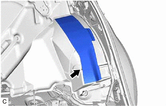
(a) w/ Silencer Sheet:
| (1) Remove the No. 2 room partition panel silencer sheet from the room partition panel insulator. |
|
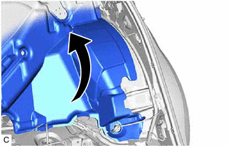
| (b) Turn back the room partition panel insulator. |
|
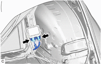
| (c) Disconnect the 2 fuel pump control ECU connectors. |
|
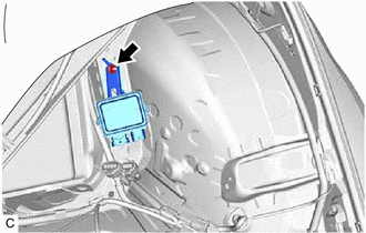
| (d) Remove the nut and fuel pump control ECU from the vehicle body. NOTICE: Do not reuse the fuel pump control ECU if it has been dropped or subjected to a severe impact. |
|
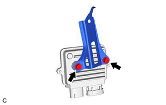
5. REMOVE FUEL PUMP CONTROL ECU BRACKET
| (a) Remove the 2 bolts and fuel pump control ECU bracket from the fuel pump control ECU. |
|
READ NEXT:
 Installation
INSTALLATION PROCEDURE 1. INSTALL FUEL PUMP CONTROL ECU BRACKET (a) Install the fuel pump control ECU bracket to the fuel pump control ECU with the 2 bolts. Torque: 4.5 N·m {46 kgf·cm, 40 in·lbf}
Components
COMPONENTS ILLUSTRATION *A for Type A - - *1 FUEL SENDER GAUGE ASSEMBLY *2 FUEL SUCTION TUBE WITH PUMP AND GAUGE ASSEMBLY ILLUSTRATION *A for Type B - - *1 FUEL
SEE MORE:
Screen Flicker or Color Distortion
PROCEDURE 1. CHECK DISPLAY SETTING (a) Reset display settings (contrast, brightness) and check that the screen appears normal. OK: The display returns to normal. OK END (DISPLAY SETTING WAS CAUSE OF MALFUNCTION) NG PROCEED TO NEXT SUSPECTED AREA SHOWN IN PROBLEM SYMPTOMS TA
Cannot Switch to Automatic ID Registration Mode
DESCRIPTION When "Change Wheel Set" is selected on the multi-information display and the "OK" switch (steering pad switch assembly) is pushed and held, the system enters ID registration mode and the tire pressure warning light blinks 3 times. The main body ECU (multiplex network body ECU) receives s
