Lexus ES: Components
COMPONENTS
ILLUSTRATION
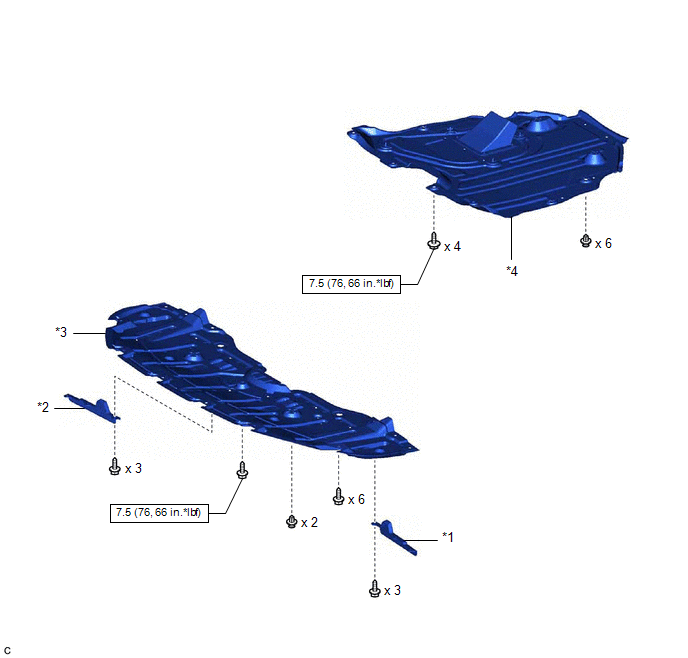
| *1 | FRONT WHEEL OPENING EXTENSION PAD LH | *2 | FRONT WHEEL OPENING EXTENSION PAD RH |
| *3 | NO. 1 ENGINE UNDER COVER | *4 | NO. 2 ENGINE UNDER COVER ASSEMBLY |
.png) | N*m (kgf*cm, ft.*lbf): Specified torque | - | - |
ILLUSTRATION
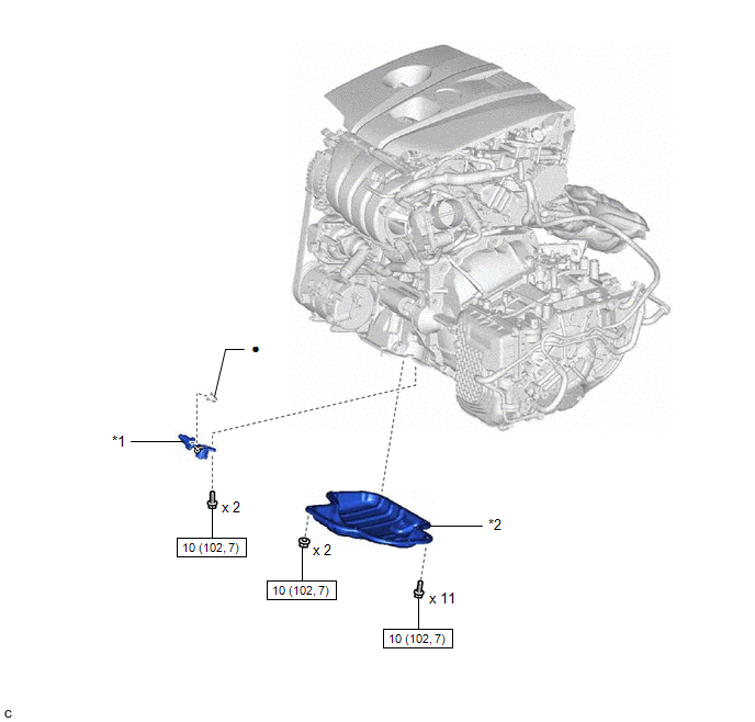
| *1 | ENGINE OIL LEVEL SENSOR | *2 | NO. 2 OIL PAN SUB-ASSEMBLY |
| | N*m (kgf*cm, ft.*lbf): Specified torque | ● | Non-reusable part |
READ NEXT:
 Removal
REMOVAL CAUTION / NOTICE / HINT NOTICE: This procedure includes the removal of small-head bolts. Refer to Small-Head Bolts of Basic Repair Hint to identify the small-head bolts. Click here PROCEDURE
Inspection
INSPECTION PROCEDURE 1. INSPECT ENGINE OIL LEVEL SENSOR (a) Measure the resistance according to the value(s) in the table below. Standard Resistance: Tester Connection Condition Specified C
Installation
INSTALLATION CAUTION / NOTICE / HINT NOTICE: This procedure includes the installation of small-head bolts. Refer to Small-Head Bolts of Basic Repair Hint to identify the small-head bolts. Click here
SEE MORE:
Installation
INSTALLATION CAUTION / NOTICE / HINT for HV Model:
When removing or installing the front disc brake caliper assembly, pushing back the disc brake piston may cause a large clearance between the brake pads and brake disc. When the brake pedal is depressed with a large clearance between the brake pa
Components
COMPONENTS ILLUSTRATION *1 CENTER INSTRUMENT CLUSTER FINISH PANEL SUB-ASSEMBLY *2 INSTRUMENT PANEL FINISH PANEL END LH *3 INSTRUMENT PANEL FINISH PANEL END RH *4 REAR UPPER CONSOLE PANEL SUB-ASSEMBLY *5 REMOTE OPERATION CONTROLLER ASSEMBLY *6 SHIFT LEVER KNOB SUB-ASSEMB
© 2016-2026 Copyright www.lexguide.net
