Lexus ES: Removal
REMOVAL
CAUTION / NOTICE / HINT
The necessary procedures (adjustment, calibration, initialization or registration) that must be performed after parts are removed and installed, or replaced during fuel main valve assembly removal/installation are shown below.
Necessary Procedures After Parts Removed/Installed/Replaced| Replaced Part or Performed Procedure | Necessary Procedure | Effect/Inoperative Function when Necessary Procedure not Performed | Link |
|---|---|---|---|
|
*: When performing learning using the Techstream.
Click here | |||
| Auxiliary battery terminal is disconnected/reconnected | Perform steering sensor zero point calibration | Lane Control System (for HV Model) | |
| Pre-collision System (for HV Model) | |||
| Parking Support Brake System (for HV Model)* | |||
| Lighting System (for HV Model) | |||
| Memorize steering angle neutral point | Parking Assist Monitor System (for HV Model) | | |
| Panoramic View Monitor System (for HV Model) | | ||
| Initialize power trunk lid system | Power Trunk Lid System (for HV Model) | | |
CAUTION:
-
Never perform work on fuel system components near any possible ignition sources.
.png)
- Vaporized fuel could ignite, resulting in a serious accident.
-
Do not perform work on fuel system components without first disconnecting the cable from the negative (-) auxiliary battery terminal.
.png)
- Sparks could cause vaporized fuel to ignite, resulting in a serious accident.
NOTICE:
- After the power switch is turned off, the radio receiver assembly records various types of memory and settings. As a result, after turning the power switch off, make sure to wait at least 85 seconds before disconnecting the cable from the negative (-) auxiliary battery terminal. (for Audio and Visual System)
- After the power switch is turned off, the radio receiver assembly records various types of memory and settings. As a result, after turning the power switch off, make sure to wait at least 85 seconds before disconnecting the cable from the negative (-) auxiliary battery terminal. (for Navigation System)
PROCEDURE
1. REMOVE FUEL SUCTION TUBE WITH PUMP AND GAUGE ASSEMBLY
Click here .gif)
2. REMOVE FUEL MAIN VALVE ASSEMBLY
(a) for Type A:
| (1) Remove the clip from the fuel suction tube with pump and gauge assembly. |
|
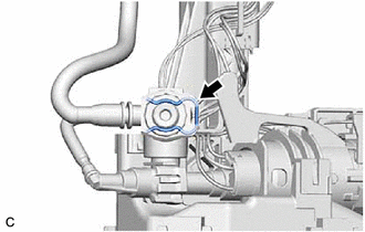
| (2) Using a screwdriver with its tip wrapped with protective tape, remove the fuel main valve assembly from the fuel suction tube with pump and gauge assembly. NOTICE:
|
|
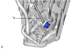
| (3) Remove the 2 O-rings from the fuel main valve assembly. |
|
.png)
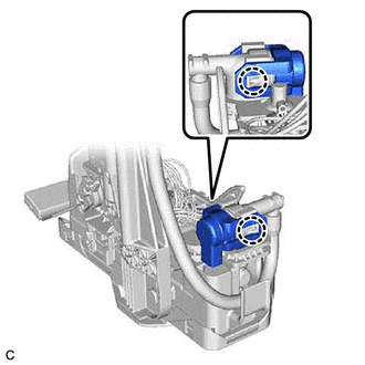
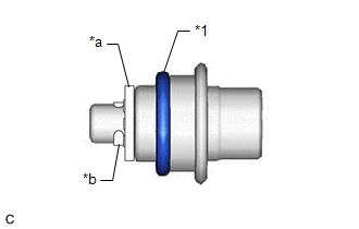
(b) for Type B:
| (1) Disengage the 2 claws and remove the fuel pressure regulator holder from the fuel suction tube with pump and gauge assembly. |
|
| (2) Using a screwdriver with its tip wrapped with protective tape, remove the fuel main valve assembly from the fuel suction tube with pump and gauge assembly. NOTICE:
|
|
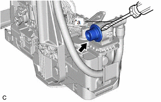
| (3) Remove the O-ring from the fuel main valve assembly. NOTICE: Do not remove the mesh and mini-clip from the fuel main valve assembly. |
|
READ NEXT:
 Installation
INSTALLATION PROCEDURE 1. INSTALL FUEL MAIN VALVE ASSEMBLY (a) for Type A: (1) Apply gasoline to 2 new O-rings. Then install the O-rings to the fuel main valve assembly. (2) Install the fuel main valv
Components
COMPONENTS ILLUSTRATION *A for EGR Valve Bracket Connection Type *B for Cylinder Head Cover Sub-assembly Connection Type *1 NO. 2 FUEL PRESSURE SENSOR *2 NO. 2 FUEL PRESSURE SENSOR
SEE MORE:
High Beam Headlight Circuit
DESCRIPTION The headlight ECU sub-assembly controls the high beam headlights. WIRING DIAGRAM except Bulb Type Turn Signal Light (for TMMK Made) for Bulb Type Turn Signal Light (for TMMK Made) CAUTION / NOTICE / HINT NOTICE:
If the headlight ECU sub-assembly LH has been replaced, it is necessary
System Diagram
SYSTEM DIAGRAM w/ Parking Assist Monitor System w/ Panoramic View Monitor System w/o Manual (SOS) Switch w/ Manual (SOS) Switch w/ Manual (SOS) Switch for 10 Speakers for 17 Speakers for 17 Speakers
