
Lexus ES: Components
Lexus ES (XZ10) Service Manual / Engine & Hybrid System / A25a-fxs (fuel) / Fuel Main Valve / Components
COMPONENTS
ILLUSTRATION
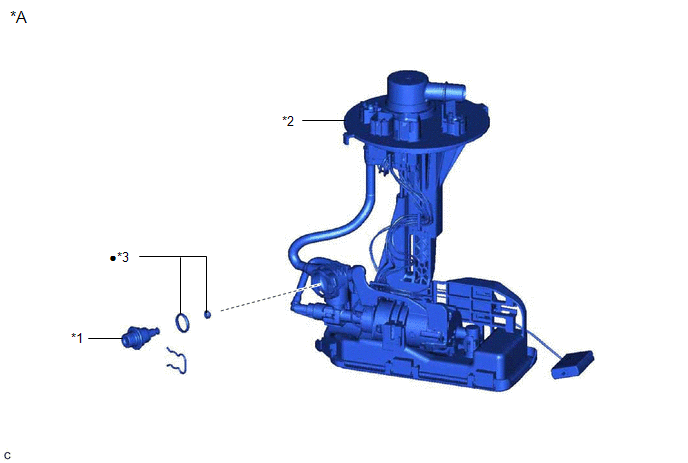
| *A | for Type A | - | - |
| *1 | FUEL MAIN VALVE ASSEMBLY | *2 | FUEL SUCTION TUBE WITH PUMP AND GAUGE ASSEMBLY |
| *3 | O-RING | - | - |
| ● | Non-reusable part | - | - |
ILLUSTRATION
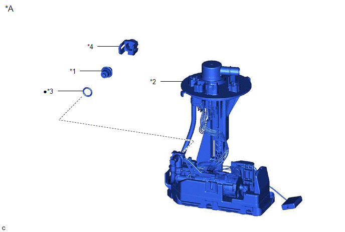
| *A | for Type B | - | - |
| *1 | FUEL MAIN VALVE ASSEMBLY | *2 | FUEL SUCTION TUBE WITH PUMP AND GAUGE ASSEMBLY |
| *3 | O-RING | *4 | FUEL PRESSURE REGULATOR HOLDER |
| ● | Non-reusable part | - | - |
READ NEXT:
 Removal
REMOVAL CAUTION / NOTICE / HINT The necessary procedures (adjustment, calibration, initialization or registration) that must be performed after parts are removed and installed, or replaced during fuel
Installation
INSTALLATION PROCEDURE 1. INSTALL FUEL MAIN VALVE ASSEMBLY (a) for Type A: (1) Apply gasoline to 2 new O-rings. Then install the O-rings to the fuel main valve assembly. (2) Install the fuel main valv
SEE MORE:
Parts Location
PARTS LOCATION ILLUSTRATION *1 OUTER MIRROR SWITCH ASSEMBLY *2 OUTER REAR VIEW MIRROR ASSEMBLY LH *3 OUTER REAR VIEW MIRROR ASSEMBLY RH *4 DEF RELAY *5 OUTER MIRROR LH *6 OUTER MIRROR RH *7 NO. 1 ENGINE ROOM RELAY BLOCK AND NO. 1 JUNCTION BLOCK ASSEMBLY - DEF FUSE
DC/DC Converter Step Up Voltage Performance (P0CA300)
DTC SUMMARY MALFUNCTION DESCRIPTION This DTC indicates that it has been detected that the VH voltage cannot be boosted as commanded due to malfunction of the boost converter system. The cause of this malfunction may be one of the following: Internal inverter malfunction
Inverter with converter as
© 2016-2026 Copyright www.lexguide.net
