Lexus ES: Installation
INSTALLATION
PROCEDURE
1. INSTALL FUEL SUCTION TUBE WITH PUMP AND GAUGE ASSEMBLY
(a) Install a new fuel suction tube set gasket to the fuel tank assembly.
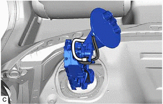
(b) Connect the fuel return vent tube sub-assembly to the fuel suction tube with pump and gauge assembly.
Click here .gif)
NOTICE:
When connecting the fuel tube connector, do not excessively pull on the fuel return vent tube sub-assembly.
| (c) Insert the fuel suction tube with pump and gauge assembly to the fuel tank assembly as shown in the illustration. |
|
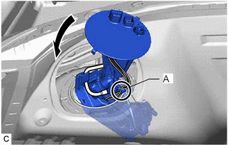
| (d) Set the part (A) of the fuel suction tube with pump and gauge assembly against the fuel tank assembly, and install the fuel suction tube with pump and gauge assembly to the fuel tank assembly as shown in the illustration. NOTICE: Be careful not to bend the arm of the fuel sender gauge assembly. |
|
(e) Align the protrusions of the fuel suction tube with pump and gauge assembly with the notches in the fuel tank assembly.
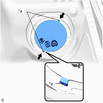
| *a | Protrusion |
.png) | Notch |
2. INSTALL FUEL PUMP GAUGE RETAINER
(a) Install the fuel pump gauge retainer.
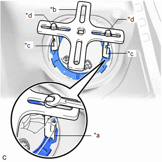
(1) While pressing down on the fuel suction tube with pump and gauge assembly, temporarily install the fuel pump gauge retainer.
| (2) Temporarily install SST (plate) and SST (claw) to the fuel pump gauge retainer. SST: 09808-01071 SST: 09808-14031 09808-01030 09808-01090 HINT: Securely insert the ends of SST (claw) into the insertion points in the fuel pump gauge retainer. |
|
(3) While firmly pressing SST (claw) into the insertion points in the fuel pump gauge retainer, tighten SST (bolt).
(4) Install SST (handle) to SST (plate).
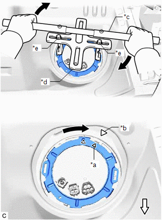
| *a | Triangle Mark (Fuel Pump Gauge Retainer) |
| *b | Triangle Mark (Fuel Tank Assembly) |
| *c | SST (Handle) |
| *d | SST (Plate) |
| *e | SST (Bolt) |
.png) | Front Side |
SST: 09808-14031
09808-01010
(5) Using SST, rotate the fuel pump gauge retainer so that the triangle mark on the fuel pump gauge retainer is aligned with the triangle mark on the fuel tank assembly to install the fuel suction tube with pump and gauge assembly to the fuel tank assembly.
NOTICE:
- Do not use any tools other than specified as this may result in damage to the fuel pump gauge retainer or fuel tank assembly.
- Do not press down on SST excessively as this may make the fuel pump gauge retainer hard to rotate, and may damage components.
- Make sure to rotate SST (handle) horizontally. If it is rotated at an angle, SST may come off.
- Do not spin SST too fast or use an impact wrench as this may result in damage to components.
- If SST comes off of the fuel pump gauge retainer, loosen SST (bolt) and reinstall SST.
- Make sure that the fuel suction tube set gasket does not come off.
(b) Engage the claw to install the No. 1 fuel tube clamp.
3. CONNECT FUEL TANK MAIN TUBE SUB-ASSEMBLY
(a) Push the fuel tube joint onto the plug of the fuel suction plate sub-assembly, then install the tube joint clip.
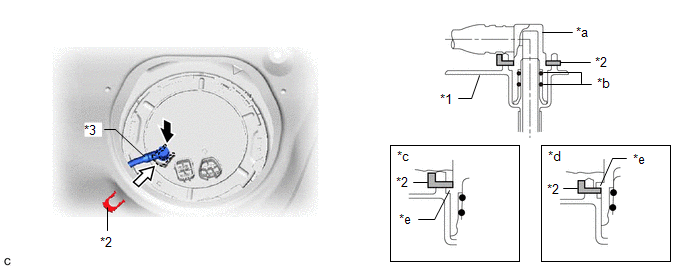
| *1 | Fuel Suction Plate Sub-assembly | *2 | Tube Joint Clip |
| *3 | Fuel Tank Main Tube Sub-assembly | - | - |
| *a | Fuel Tube Joint | *b | O-ring |
| *c | Correct | *d | Incorrect |
| *e | Collar | - | - |
| | Insert | | Insert |
NOTICE:
- Check that there are no scratches or foreign matter around the connecting parts of the fuel tube joint and plug before performing this work.
- Check that the fuel tube joint is securely inserted to the end.
- Check that the tube joint clip is on the collar of the fuel tube joint.
- After installing the tube joint clip, check that the fuel tank main tube sub-assembly is securely connected by pulling on it.
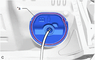
4. INSTALL REAR FLOOR SERVICE HOLE COVER
(a) Remove any remaining butyl tape from the rear floor service hole cover and vehicle body.
(b) Clean the installation surfaces of the rear floor service hole cover and vehicle body.
(c) Connect the 2 fuel suction tube with pump and gauge assembly connectors.
| (d) Install the rear floor service hole cover with new butyl tape. NOTICE: Securely install the rear floor service hole cover. |
|
5. CONNECT CABLE TO NEGATIVE BATTERY TERMINAL
Click here
6. INSPECT FOR FUEL LEAK
Click here
7. INSTALL REAR SEAT CUSHION LOCK HOOK
Click here
8. INSTALL REAR SEAT CUSHION ASSEMBLY
Click here
9. PERFORM INITIALIZATION
(a) Perform "Inspection After Repair" after replacing the fuel pump.
Click here
READ NEXT:
 Fuel Pump (for High Pressure)
ComponentsCOMPONENTS ILLUSTRATION *1 NO. 1 FUEL PIPE SUB-ASSEMBLY *2 FUEL PUMP ASSEMBLY *3 FUEL TUBE SUB-ASSEMBLY *4 FUEL PUMP LIFTER ASSEMBLY *5 FUEL PUMP FLANGE *6 FUE
Fuel Pump Ecu
ComponentsCOMPONENTS ILLUSTRATION *A w/ Silencer Sheet - - *1 FUEL PUMP CONTROL ECU *2 FUEL PUMP CONTROL ECU BRACKET *3 REAR SEAT SIDE GARNISH LH *4 REAR DOOR SCUFF PLAT
SEE MORE:
Left Front Wheel ABS Hold Solenoid Control Circuit Short to Battery (C12A512,...,C12B049)
DESCRIPTION The ABS solenoid relay and solenoid valves are built into the brake actuator assembly. The front solenoid valve LH controls the brake fluid pressure of the front wheel cylinder LH of the vehicle. When this DTC is stored, the fail-safe function operates and the ABS solenoid relay is turne
Hybrid/EV Battery Negative Contactor Actuator Stuck Closed (P0AA373)
DTC SUMMARY MALFUNCTION DESCRIPTION The hybrid vehicle control ECU detects a stuck closed malfunction of a system main relay on the HV battery negative side. The cause of this malfunction may be one of the following: Inverter voltage sensor (VH) internal circuit malfunction
Voltage sensor (VH) ma
