Lexus ES: Fuel Pump (for High Pressure)
Components
COMPONENTS
ILLUSTRATION
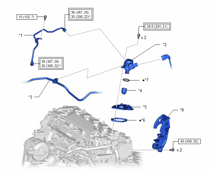
| *1 | NO. 1 FUEL PIPE SUB-ASSEMBLY | *2 | FUEL PUMP ASSEMBLY |
| *3 | FUEL TUBE SUB-ASSEMBLY | *4 | FUEL PUMP LIFTER ASSEMBLY |
| *5 | FUEL PUMP FLANGE | *6 | FUEL PUMP SPACER GASKET |
| *7 | O-RING | *8 | FUEL PUMP PROTECTOR |
.png) | Tightening torque for "Major areas involving basic vehicle performance such as moving/turning/stopping": N*m (kgf*cm, ft.*lbf) | .png) | N*m (kgf*cm, ft.*lbf): Specified torque |
| * | For use with a union nut wrench | ● | Non-reusable part |
On-vehicle Inspection
ON-VEHICLE INSPECTION
PROCEDURE
1. FUEL PUMP ASSEMBLY OPERATION
(a) Check fuel pressure.
(1) Connect the Techstream to the DLC3.
(2) Start the engine.
(3) Turn the Techstream on.
(4) Enter the following menus: Powertrain / Engine / Active Test / Control the Target Fuel Pressure Offset.
Powertrain > Engine > Active Test| Active Test Display |
|---|
| Control the Target Fuel Pressure Offset |
| Data List Display |
|---|
| Fuel Pressure (High) |
(5) Select the Data List item: Fuel Pressure (High).
(6) Check that the fuel pressure fluctuates when the target fuel pressure changes.
HINT:
The target fuel pressure operation decreases the target fuel pressure by 12.5% or increases the target fuel pressure by 24.8%.
If the result is not as specified, replace the fuel pump assembly or fuel pressure sensor.
(b) Check operating sound.
(1) Remove the No. 1 engine cover sub-assembly.
Click here .gif)
(2) Start the engine.
(3) Using a sound scope, check the operating sound of the fuel pump assembly.
If no sound can be heard, check the fuel pump assembly, wire harness and ECM.
(4) Stop the engine.
(5) Install the No. 1 engine cover sub-assembly.
Click here
Inspection
INSPECTION
PROCEDURE
1. INSPECT FUEL PUMP ASSEMBLY
| (a) Measure the resistance according to the value(s) in the table below. Standard Resistance:
If the result is not as specified, replace the fuel pump assembly. |
|
.png)
READ NEXT:
 Fuel Pump Ecu
ComponentsCOMPONENTS ILLUSTRATION *A w/ Silencer Sheet - - *1 FUEL PUMP CONTROL ECU *2 FUEL PUMP CONTROL ECU BRACKET *3 REAR SEAT SIDE GARNISH LH *4 REAR DOOR SCUFF PLAT
Components
COMPONENTS ILLUSTRATION *1 FUEL SUCTION TUBE WITH PUMP AND GAUGE ASSEMBLY *2 FUEL SENDER GAUGE ASSEMBLY ILLUSTRATION *1 FUEL PUMP GAUGE RETAINER *2 FUEL TANK VENT TUBE ASSEMBLY
SEE MORE:
Data List / Active Test
DATA LIST / ACTIVE TEST DATA LIST HINT: Using the Techstream to read the Data List allows the values or states of switches, sensors, actuators and other items to be read without removing any parts. This non-intrusive inspection can be very useful because intermittent conditions or signals may be dis
Components
COMPONENTS ILLUSTRATION *A for EGR Valve Bracket Connection Type *B for Cylinder Head Cover Sub-assembly Connection Type *1 FUEL DELIVERY PIPE *2 FUEL INJECTOR SEAL *3 DIRECT FUEL INJECTOR ASSEMBLY *4 NO. 1 FUEL PIPE SUB-ASSEMBLY *5 NO. 3 FUEL INJECTOR BACK-UP RIN
