Lexus ES: Fuel Pump Ecu
Components
COMPONENTS
ILLUSTRATION
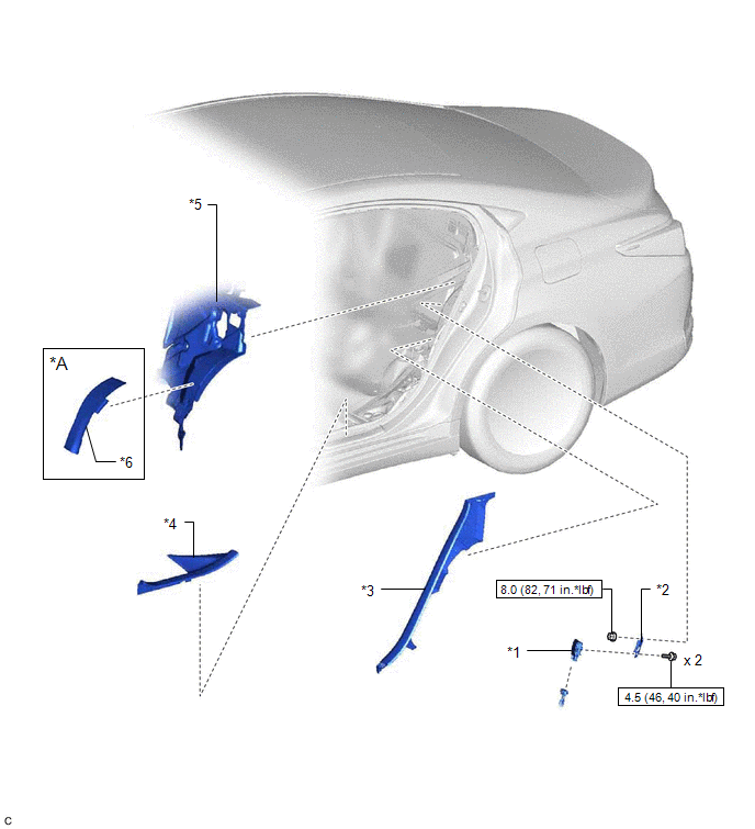
| *A | w/ Silencer Sheet | - | - |
| *1 | FUEL PUMP CONTROL ECU | *2 | FUEL PUMP CONTROL ECU BRACKET |
| *3 | REAR SEAT SIDE GARNISH LH | *4 | REAR DOOR SCUFF PLATE LH |
| *5 | ROOM PARTITION PANEL INSULATOR | *6 | NO. 2 ROOM PARTITION PANEL SILENCER SHEET |
.png) | N*m (kgf*cm, ft.*lbf): Specified torque | - | - |
Installation
INSTALLATION
PROCEDURE
1. INSTALL FUEL PUMP CONTROL ECU BRACKET
(a) Install the fuel pump control ECU bracket to the fuel pump control ECU with the 2 bolts.
Torque:
4.5 N·m {46 kgf·cm, 40 in·lbf}
2. INSTALL FUEL PUMP CONTROL ECU
(a) Install the fuel pump control ECU to the vehicle body with the nut.
Torque:
8.0 N·m {82 kgf·cm, 71 in·lbf}
(b) Connect the 2 fuel pump control ECU connectors.
(c) Return the room partition panel insulator to its original position.
(d) w/ Silencer Sheet:
(1) Install the No. 2 room partition panel silencer sheet to the room partition panel insulator.
3. INSTALL REAR SEAT SIDE GARNISH LH
Click here .gif)
4. INSTALL REAR DOOR SCUFF PLATE LH
Click here
5. INSTALL REAR SEAT ASSEMBLY
Click here
READ NEXT:
 Components
COMPONENTS ILLUSTRATION *1 FUEL SUCTION TUBE WITH PUMP AND GAUGE ASSEMBLY *2 FUEL SENDER GAUGE ASSEMBLY ILLUSTRATION *1 FUEL PUMP GAUGE RETAINER *2 FUEL TANK VENT TUBE ASSEMBLY
Inspection
INSPECTION PROCEDURE 1. INSPECT FUEL SENDER GAUGE ASSEMBLY CAUTION: Perform the inspection in a well-ventilated area. Do not perform the inspection near an open flame. (a) Check that the float moves s
SEE MORE:
Lost Communication with ECM / PCM "A" (U0100,U0125,U0126,U0129,U0142,U0293)
DESCRIPTION These DTCs are stored if there is a malfunction in the CAN communication system connected to the blind spot monitor sensor. HINT: If CAN communication system DTCs are stored, they may also be stored for other systems. Blind Spot Monitor Master DTC No. Detection Item DTC Detection
Software Incompatibility with Body Control Module Not Programmed (U032251)
DESCRIPTION If the forward recognition camera cannot verify the vehicle information sent from the main body ECU (multiplex network body ECU), the forward recognition camera stores DTC U032251. DTC No. Detection Item DTC Detection Condition Trouble Area MIL DTC Output from U032251
