Lexus ES: Hybrid/EV Battery Negative Contactor Actuator Stuck Closed (P0AA373)
DTC SUMMARY
MALFUNCTION DESCRIPTION
The hybrid vehicle control ECU detects a stuck closed malfunction of a system main relay on the HV battery negative side.
The cause of this malfunction may be one of the following:
- Voltage sensor (VH) malfunction
- Motor generator control ECU (MG ECU) malfunction
- Communication (wire harness) malfunction
- HV battery junction block assembly malfunction
- Hybrid vehicle control ECU malfunction
- HV battery junction block assembly malfunction
- Low voltage wire harness malfunction
- Low voltage connector malfunction
DESCRIPTION
Refer to the description for DTC P0AE411.
Click here .gif)
| DTC No. | Detection Item | DTC Detection Condition | Trouble Area | MIL | Warning Indicate |
|---|---|---|---|---|---|
| P0AA373 | Hybrid/EV Battery Negative Contactor Actuator Stuck Closed | Even the system main relay of HV battery negative (-) terminal side is turned off, the inverter voltage (VH) does not drop. (1 trip detection logic) |
| Does not come on | Master Warning Light: Comes on |
| DTC No. | Data List |
|---|---|
| P0AA373 |
|
CONFIRMATION DRIVING PATTERN
HINT:
After repair has been completed, clear the DTC and then check that the vehicle has returned to normal by performing the following All Readiness check procedure.
Click here
- Connect the Techstream to the DLC3.
- Turn the power switch on (IG) and turn the Techstream on.
- Clear the DTCs (even if no DTCs are stored, perform the clear DTC procedure).
- Turn the power switch off and wait for 2 minutes or more.
- Turn the power switch on (IG) and turn the Techstream on.
-
Turn the power switch on (READY) and wait for 3 minutes or more.
HINT:
According to the display on the Techstream, read the Data List and monitor the values of "Hybrid Battery Voltage" and "VL-Voltage before Boosting" for 3 minutes. If the difference between "Hybrid Battery Voltage" and "VL-Voltage before Boosting" is always less than 100 V, the vehicle has returned to normal.
- Enter the following menus: Powertrain / Hybrid Control / Utility / All Readiness.
-
Check the DTC judgment result.
HINT:
- If the judgment result shows NORMAL, the system is normal.
- If the judgment result shows ABNORMAL, the system has a malfunction.
- If the judgment result shows INCOMPLETE or N/A, perform driving pattern again.
WIRING DIAGRAM
Refer to the wiring diagram for the HV Battery High-voltage Line Circuit.
Click here
CAUTION / NOTICE / HINT
CAUTION:
-
Before the following operations are conducted, take precautions to prevent electric shock by turning the power switch off, wearing insulated gloves, and removing the service plug grip from HV battery.
.png)
- Inspecting the high-voltage system
- Disconnecting the low voltage connector of the inverter with converter assembly
- Disconnecting the low voltage connector of the HV battery
-
To prevent electric shock, make sure to remove the service plug grip to cut off the high voltage circuit before servicing the vehicle.

-
After removing the service plug grip from the HV battery, put it in your pocket to prevent other technicians from accidentally reconnecting it while you are working on the high-voltage system.

-
After removing the service plug grip, wait for at least 10 minutes before touching any of the high-voltage connectors or terminals. After waiting for 10 minutes, check the voltage at the terminals in the inspection point in the inverter with converter assembly. The voltage should be 0 V before beginning work.
Click here
HINT:
Waiting for at least 10 minutes is required to discharge the high-voltage capacitor inside the inverter with converter assembly.

*a
Without waiting for 10 minutes
-
Make sure to insulate the high-voltage connectors and terminals of the HV battery with insulating tape after removing it.
If the HV battery stored without insulating the connectors and terminals, electric shock or fire may result.
NOTICE:
-
After turning the power switch off, waiting time may be required before disconnecting the cable from the negative (-) auxiliary battery terminal. Therefore, make sure to read the disconnecting the cable from the negative (-) auxiliary battery terminal notices before proceeding with work.
Click here
- If the DTCs are cleared or the cable is disconnected and reconnected to the negative (-) auxiliary battery terminal before performing repairs, turning the power switch on (READY) may cause a malfunction. Do not turn the power switch on (READY).
HINT:
If DTC P0AA373 is output, the power switch cannot be turned on (READY).
PROCEDURE
| 1. | CHECK DTC OUTPUT (HYBRID CONTROL, MOTOR GENERATOR) |
(a) Connect the Techstream to the DLC3.
(b) Turn the power switch on (IG).
(c) Enter the following menus: Powertrain / Hybrid Control and Motor Generator / Trouble Codes.
(d) Check for DTCs.
Powertrain > Hybrid Control > Trouble Codes Powertrain > Motor Generator > Trouble Codes| Result | Proceed to |
|---|---|
| P0AA373 only is output, or DTCs except the ones in the table below are also output. | A |
| DTCs of hybrid control system in the tables below are output. | B |
| DTCs of motor generator control system in the tables below are output. | C |
| Malfunction Content | System | Relevant DTC | |
|---|---|---|---|
| Microcomputer malfunction | Hybrid control system | P060647 | Hybrid/EV Powertrain Control Module Processor Watchdog / Safety MCU Failure |
| P060687 | Hybrid/EV Powertrain Control Module Processor to Monitoring Processor Missing Message | ||
| P060A47 | Hybrid/EV Powertrain Control Module Monitoring Processor Watchdog / Safety MCU Failure | ||
| P060A87 | Hybrid/EV Powertrain Control Module Processor from Monitoring Processor Missing Message | ||
| P0A1B49 | Drive Motor "A" Control Module Internal Electronic Failure | ||
| P1C9E9F | Hybrid/EV System Reset Stuck Off | ||
| P0AFC96 | Hybrid/EV Battery Sensor Module Component Internal Failure | ||
| P0AFC00 | Hybrid/EV Battery Sensor Module | ||
| Motor generator control system | P0A1B1F | Generator Control Module Circuit Intermittent | |
| P0A1A47 | Generator Control Module Watchdog / Safety μC Failure | ||
| P0A1A49 | Generator Control Module Internal Electronic Failure | ||
| P1C2A1C | Generator A/D Converter Circuit Circuit Voltage Out of Range | ||
| P1C2A49 | Generator A/D Converter Circuit Internal Electronic Failure | ||
| P1C2B1C | Drive Motor "A" Control Module A/D Converter Circuit Voltage Out of Range | ||
| P1C2B49 | Drive Motor "A" Control Module A/D Converter Circuit Internal Electronic Failure | ||
| P1CAC49 | Generator Position Sensor Internal Electronic Failure | ||
| P1CAD49 | Drive Motor "A" Position Sensor Internal Electronic Failure | ||
| P1CAF38 | Generator Position Sensor REF Signal Cycle Malfunction Signal Frequency Incorrect | ||
| P1CB038 | Drive Motor "A" Position Sensor REF Signal Frequency Incorrect | ||
| P313383 | Communication Error from Generator to Drive Motor "A" Value of Signal Protection Calculation Incorrect | ||
| P313386 | Communication Error from Generator to Drive Motor "A" Signal Invalid | ||
| P313387 | Communication Error from Generator to Drive Motor "A" Missing Message | ||
| Power source circuit malfunction | Hybrid control system | P0AFC16 | Hybrid/EV Battery Sensor Module Circuit Voltage Below Threshold |
| Motor generator control system | P06D61C | Generator Control Module Offset Power Circuit Voltage Out of Range | |
| P06B01C | Generator Control Module Position Sensor REF Power Source Circuit Voltage Out of Range | ||
| Communication system malfunction | Hybrid control system | P312387 | Lost Communication with Drive Motor Control Module "A" from Hybrid/EV Control Module Missing Message |
| U029A87 | Lost Communication with Hybrid/EV Battery Sensor Module Missing Message | ||
| Sensor and actuator circuit malfunction | Hybrid control system | P0AD911 | Hybrid/EV Battery Positive Contactor Circuit Short to Ground |
| P0AD915 | Hybrid/EV Battery Positive Contactor Circuit Short to Auxiliary Battery or Open | ||
| P0ADD11 | Hybrid/EV Battery Negative Contactor Circuit Short to Ground | ||
| P0ADD15 | Hybrid/EV Battery Negative Contactor Circuit Short to Auxiliary Battery or Open | ||
| P0AE411 | Hybrid/EV Battery Precharge Contactor Circuit Short to Ground | ||
| P0AE415 | Hybrid/EV Battery Precharge Contactor Circuit Short to Auxiliary Battery or Open | ||
| P0B3B14 | Hybrid/EV Battery Voltage Sensor "A" Circuit Short to Ground or Open | ||
| P0B4014 | Hybrid/EV Battery Voltage Sensor "B" Circuit Short to Ground or Open | ||
| P0B4514 | Hybrid/EV Battery Voltage Sensor "C" Circuit Short to Ground or Open | ||
| P0B4A14 | Hybrid/EV Battery Voltage Sensor "D" Circuit Short to Ground or Open | ||
| P0B4F14 | Hybrid/EV Battery Voltage Sensor "E" Circuit Short to Ground or Open | ||
| P0B5414 | Hybrid/EV Battery Voltage Sensor "F" Circuit Short to Ground or Open | ||
| P0B5914 | Hybrid/EV Battery Voltage Sensor "G" Circuit Short to Ground or Open | ||
| P0B5E14 | Hybrid/EV Battery Voltage Sensor "H" Circuit Short to Ground or Open | ||
| P0B6314 | Hybrid/EV Battery Voltage Sensor "I" Circuit Short to Ground or Open | ||
| P0B6814 | Hybrid/EV Battery Voltage Sensor "J" Circuit Short to Ground or Open | ||
| P0B6D14 | Hybrid/EV Battery Voltage Sensor "K" Circuit Short to Ground or Open | ||
| P0B7214 | Hybrid/EV Battery Voltage Sensor "L" Circuit Short to Ground or Open | ||
| P308A13 | Hybrid/EV Battery Voltage Sensor All Circuit Open | ||
| P0AFC62 | Hybrid/EV Battery Sensor Module Signal Compare Failure | ||
| P308A12 | Hybrid/EV Battery Voltage Sensor All Circuit Short to Auxiliary Battery | ||
| Motor generator control system | P0A3F16 | Drive Motor "A" Position Sensor Circuit Voltage Below Threshold | |
| P0A4B16 | Generator Position Sensor Circuit Voltage Below Threshold | ||
| P0A4B21 | Generator Position Sensor Signal Amplitude < Minimum | ||
| P0A4B22 | Generator Position Sensor Signal Amplitude > Maximum | ||
| P0C5013 | Drive Motor "A" Position Sensor Circuit "A" Circuit Open | ||
| P0C5016 | Drive Motor "A" Position Sensor Circuit "A" Circuit Voltage Below Threshold | ||
| P0C5017 | Drive Motor "A" Position Sensor Circuit "A" Circuit Voltage Above Threshold | ||
| P0C5A13 | Drive Motor "A" Position Sensor Circuit "B" Circuit Open | ||
| P0C5A16 | Drive Motor "A" Position Sensor Circuit "B" Circuit Voltage Below Threshold | ||
| P0C5A17 | Drive Motor "A" Position Sensor Circuit "B" Circuit Voltage Above Threshold | ||
| P0C6413 | Generator Position Sensor Circuit "A" Circuit Open | ||
| P0C6416 | Generator Position Sensor Circuit "A" Circuit Voltage Below Threshold | ||
| P0C6417 | Generator Position Sensor Circuit "A" Circuit Voltage Above Threshold | ||
| P0C6913 | Generator Position Sensor Circuit "B" Circuit Open | ||
| P0C6916 | Generator Position Sensor Circuit "B" Circuit Voltage Below Threshold | ||
| P0C6917 | Generator Position Sensor Circuit "B" Circuit Voltage Above Threshold | ||
| System malfunction | Hybrid control system | P0C7600 | Hybrid/EV Battery System Discharge Time Too Long |
| P0D2D1C | Drive Motor "A" Inverter Voltage Sensor Voltage Out of Range | ||
| P1C8349 | High Voltage Power Resource Circuit Voltage Sensor after Boosting Malfunction | ||
| Motor generator control system | P0D2D16 | Drive Motor "A" Inverter Voltage Sensor (VH) Circuit Voltage Below Threshold | |
| P0D2D17 | Drive Motor "A" Inverter Voltage Sensor (VH) Circuit Voltage Above Threshold | ||
| P1CB69E | Drive Motor "A" Inverter Voltage Sensor (VH) Stuck On | ||
HINT:
-
P0AA373 may be output as a result of the malfunction indicated by the DTCs above.
- The chart above is listed in inspection order of priority.
- Check DTCs that are output at the same time by following the listed order. (The main cause of the malfunction can be determined without performing unnecessary inspections.)
(e) Turn the power switch off.
| B | .gif) | GO TO DTC CHART (HYBRID CONTROL SYSTEM) |
| C | | GO TO DTC CHART (MOTOR GENERATOR CONTROL SYSTEM) |
|
.gif)
| 2. | CHECK FREEZE FRAME DATA (HYBRID CONTROL) |
(a) Connect the Techstream to the DLC3.
(b) Turn the power switch on (IG).
(c) Enter the following menus: Powertrain / Hybrid Control / Trouble Codes.
(d) Read the freeze frame data of DTC P0AA373.
Powertrain > Hybrid Control > Trouble CodesNOTICE:
As freeze frame data is stored immediately before and after a DTC is stored, make sure to only read the values for the moment the DTC was stored ("0(s)").
| Result | Proceed to |
|---|---|
| Difference between "VL-Voltage before Boosting" and "VH-Voltage after Boosting" is less than 76 V. | A |
| Difference between "VL-Voltage before Boosting" and "VH-Voltage after Boosting" is 76 V or more. | B |
HINT:
If VH-Voltage after Boosting is output even when an off command is being sent to the system main relay (positive side), P0AA373 is output. If the difference between the "VL-Voltage before Boosting" and the "VH-Voltage after Boosting" is large, it is determined that there is an inverter (VH sensor) malfunction.
(e) Turn the power switch off.
| B | | REPLACE INVERTER WITH CONVERTER ASSEMBLY |
|
| 3. | CHECK CONNECTOR CONNECTION CONDITION (HYBRID VEHICLE CONTROL ECU CONNECTOR) |
Click here
| OK | | GO TO STEP 5 |
|
| 4. | CONNECT SECURELY |
|
| 5. | CHECK CONNECTOR CONNECTION CONDITION (FLOOR WIRE CONNECTOR) |
Click here
| Result | Proceed to |
|---|---|
| OK | A |
| NG (The connector is not connected securely.) | B |
| NG (The terminals are not making secure contact or are deformed, or water or foreign matter exists in the connector.) | C |
| A | | GO TO STEP 8 |
| C | | GO TO STEP 7 |
|
| 6. | CONNECT SECURELY |
| NEXT | | GO TO STEP 8 |
| 7. | REPAIR OR REPLACE HARNESS OR CONNECTOR |
|
| 8. | CHECK CONNECTOR CONNECTION CONDITION (HV BATTERY JUNCTION BLOCK ASSEMBLY CONNECTOR) |
Click here
| OK | | GO TO STEP 10 |
|
| 9. | CONNECT SECURELY |
|
| 10. | CHECK GROUND WIRE CONNECTION CONDITION (SMR ACTIVATION LOW-VOLTAGE CIRCUIT) |
Click here
| OK | | GO TO STEP 12 |
|
| 11. | CONNECT SECURELY |
|
| 12. | CHECK HARNESS AND CONNECTOR (HYBRID VEHICLE CONTROL ECU - HV BATTERY JUNCTION BLOCK ASSEMBLY) |
CAUTION:
Be sure to wear insulated gloves.
(a) Check that the service plug grip is not installed.
NOTICE:
After removing the service plug grip, do not turn the power switch on (READY), unless instructed by the repair manual because this may cause a malfunction.
(b) Remove the No. 1 HV battery cover panel RH.
Click here
(c) Disconnect the N22 HV battery junction block assembly connector.
(d) Disconnect the G59 hybrid vehicle control ECU connector.
| (e) Measure the resistance according to the value(s) in the table below. Standard Resistance (Check for Open):
Standard Resistance (Check for Short):
|
|
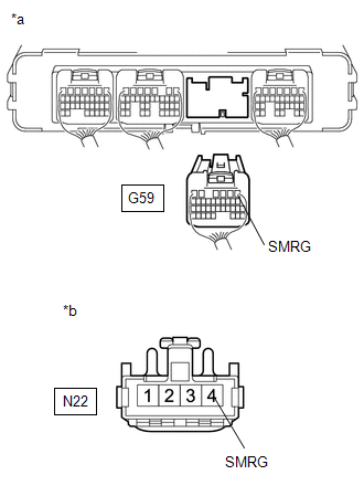
(f) Reconnect the G59 hybrid vehicle control ECU connector.
(g) Reconnect the N22 HV battery junction block assembly connector.
(h) Install the No. 1 HV battery cover panel RH.
| OK | | GO TO STEP 14 |
|
| 13. | REPAIR OR REPLACE HARNESS OR CONNECTOR |
|
| 14. | CHECK HARNESS AND CONNECTOR (HV BATTERY JUNCTION BLOCK ASSEMBLY - BODY GROUND) |
Click here
| OK | | GO TO STEP 16 |
|
| 15. | REPAIR OR REPLACE HARNESS OR CONNECTOR |
|
| 16. | INSPECT HV BATTERY JUNCTION BLOCK ASSEMBLY (SMRG) |
CAUTION:
Be sure to wear insulated gloves.
(a) Check that the service plug grip is not installed.
NOTICE:
After removing the service plug grip, do not turn the power switch on (READY), unless instructed by the repair manual because this may cause a malfunction.
(b) Remove the No. 1 HV battery cover panel RH.
Click here
(c) Disconnect the N22 HV battery junction block assembly connector.
(d) Measure the resistance according to the value(s) in the table below.
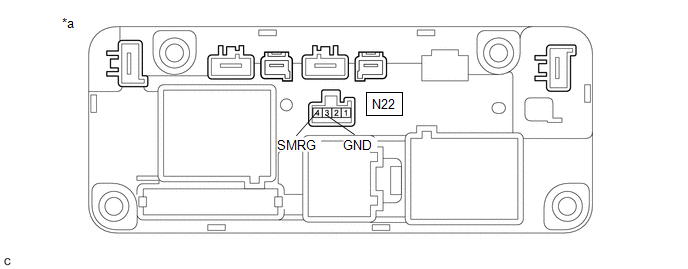
| *a | Component without harness connected (HV Battery Junction Block Assembly) | - | - |
Standard Resistance:
| Tester Connection | Condition | Specified Condition |
|---|---|---|
| N22-4 (SMRG) - N22-3 (GND) | -40 to 80°C (-40 to 176°F) | 25.0 to 59.0 Ω |
(e) Reconnect the N22 HV battery junction block assembly connector.
(f) Install the No. 1 HV battery cover panel RH.
| NG | | GO TO STEP 19 |
|
| 17. | CHECK HV BATTERY JUNCTION BLOCK ASSEMBLY (SMRG) |
CAUTION:
Be sure to wear insulated gloves.
(a) Check that the service plug grip is not installed.
NOTICE:
After removing the service plug grip, do not turn the power switch on (READY), unless instructed by the repair manual because this may cause a malfunction.
(b) Remove the No. 1 HV battery cover panel RH.
Click here
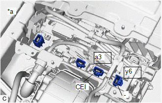
| (c) Disconnect the 2 HV floor under wire connectors from the HV battery junction block assembly. |
|
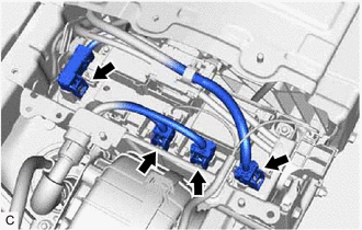
(d) Disconnect the 2 HV battery high voltage connectors from the HV battery junction block assembly.
NOTICE:
Insulate each disconnected high-voltage connector with insulating tape. Wrap the connector from the wire harness side to the end of the connector.
| (e) Measure the resistance according to the value(s) in the table below. Standard Resistance:
HINT:
|
|
(f) Reconnect the 2 HV battery high voltage connectors.
(g) Reconnect the 2 HV floor under wire connectors.
(h) Install the No. 1 HV battery cover panel RH.
| Result | Judgment | Proceed to |
|---|---|---|
| OK | Past malfunction | A |
| NG | Present malfunction | B |
| B | | GO TO STEP 20 |
|
| 18. | REPLACE HV BATTERY JUNCTION BLOCK ASSEMBLY |
Click here
| NEXT | | GO TO STEP 21 |
| 19. | REPLACE HV BATTERY JUNCTION BLOCK ASSEMBLY |
Click here
| NEXT | | GO TO STEP 21 |
| 20. | REPLACE HV BATTERY JUNCTION BLOCK ASSEMBLY |
Click here
|
| 21. | CHECK HYBRID VEHICLE CONTROL ECU (CHECK FOR NORMAL OPERATION) |
Click here
| Result | Proceed to |
|---|---|
| Difference between "Hybrid Battery Voltage" and "VL-Voltage before Boosting" is always less than 100 V. | A |
| Difference between "Hybrid Battery Voltage" and "VL-Voltage before Boosting" is 100 V or more. | B |
| A | | END |
| B | | REPLACE HYBRID VEHICLE CONTROL ECU AND HV BATTERY JUNCTION BLOCK ASSEMBLY |
READ NEXT:
 Hybrid/EV Battery Voltage System Isolation Internal Electronic Failure (P0AA649,P1C7C49-P1C7F49)
DESCRIPTION The hybrid vehicle control ECU monitors the battery voltage sensor and detects insulation malfunctions in the high-voltage system. DTC No. Detection Item DTC Detection Condition T
Hybrid/EV Battery Voltage Isolation Sensor Circuit Internal Electronic Failure (P0AA749)
DESCRIPTION The hybrid vehicle control ECU monitors the insulation monitoring circuit located in the battery voltage sensor and detects malfunctions. DTC No. Detection Item DTC Detection Condit
Hybrid/EV Battery Air Temperature Sensor "A" Circuit Short to Ground (P0AAC11,P0AAC15)
DESCRIPTION The inlet air temperature sensor (battery) is mounted on the HV battery. The resistance of the sensor varies in accordance with changes in the intake air temperature. The characteristics o
SEE MORE:
Disassembly
DISASSEMBLY CAUTION / NOTICE / HINT NOTICE: Before installation of each part, thoroughly clean and dry it. Then apply gear oil to it. Do not use alkaline chemicals to clean aluminum parts, rubber parts or ring gear set bolts. Also, do not use non-residue solvent or other cleaning oils to clean O-rin
How To Proceed With Troubleshooting
CAUTION / NOTICE / HINT HINT:
Use the following procedure to troubleshoot the parking assist monitor system.
*: Use the Techstream.
PROCEDURE 1. VEHICLE BROUGHT TO WORKSHOP
NEXT 2. CUSTOMER PROBLEM ANALYSIS (a) Ask the customer about the problems and the co
