Lexus ES: Installation
INSTALLATION
PROCEDURE
1. INSTALL CAMSHAFT TIMING GEAR BOLT
(a) Make sure that the No. 1 cylinder is at TDC/compression.
HINT:
Check that the cutout of the camshaft timing gear assembly is at the top and align the timing mark (cutout) of the crankshaft pulley with the timing mark on the timing chain cover assembly.
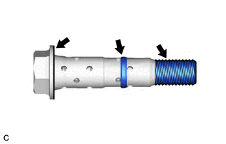
| (b) Apply engine oil to the areas of the camshaft timing gear bolt shown in the illustration. |
|
(c) While holding the crankshaft pulley, temporarily install the camshaft timing gear bolt.
Torque:
10 N·m {102 kgf·cm, 7 ft·lbf}
NOTICE:
- If the camshaft timing gear bolt has been struck or dropped, replace it.
- If there is any abnormal resistance when temporarily installing the camshaft timing gear bolt, loosen it and make sure that the No. 1 cylinder is at TDC/compression, and then temporarily install the camshaft timing gear bolt again.
HINT:
Make sure that the flange part of the camshaft timing gear bolt contacts the entire circumference of the camshaft timing gear assembly.
(d) While holding the crankshaft pulley, loosen the camshaft timing gear bolt 60 to 180°.
(e) Turn the crankshaft pulley counterclockwise 30 to 90°.
(f) While holding the crankshaft pulley, tighten the camshaft timing gear bolt.
Torque:
95 N·m {969 kgf·cm, 70 ft·lbf}
NOTICE:
Do not use an impact wrench.
2. INSTALL CAMSHAFT TIMING OIL CONTROL SOLENOID ASSEMBLY (for Intake Side of Bank 1)
Click here .gif)
3. INSPECT FOR ENGINE OIL LEAK
Click here
4. INSTALL V-BANK COVER SUB-ASSEMBLY
Click here
5. INSTALL FRONT FENDER APRON SEAL RH
Click here
6. INSTALL FRONT WHEEL RH
Click here
READ NEXT:
 Components
COMPONENTS ILLUSTRATION *1 CAMSHAFT TIMING GEAR BOLT *2 O-RING *3 CAMSHAFT TIMING OIL CONTROL SOLENOID ASSEMBLY (for Intake Side of Bank 2) - - N*m (kgf*cm, ft.*lbf): Specif
Removal
REMOVAL CAUTION / NOTICE / HINT The necessary procedures (adjustment, calibration, initialization or registration) that must be performed after parts are removed and installed, or replaced during cams
SEE MORE:
ACIS Control Circuit
DESCRIPTION ACIS (Acoustic Control Induction System) controls the opening and closing the intake air control valve sub-assembly built into the intake air surge tank assembly to increase the intake efficiency according to the engine load. When the engine speed is between 0 and 4300 rpm and the thrott
Installation
INSTALLATION PROCEDURE 1. INSTALL NO. 1 FUEL TANK PROTECTOR SUB-ASSEMBLY (a) Engage the 2 claws to install the No. 1 fuel tank protector sub-assembly to the fuel tank assembly. 2. INSTALL FUEL TANK MAIN TUBE SUB-ASSEMBLY (a) Engage the 2 clamps to install the fuel tank main tube sub-assembly to the
