Lexus ES: Removal
REMOVAL
CAUTION / NOTICE / HINT
The necessary procedures (adjustment, calibration, initialization, or registration) that must be performed after parts are removed and installed, or replaced during rear stabilizer bar removal/installation are shown below.
Necessary Procedures After Parts Removed/Installed/Replaced (for HV Model:)| Replaced Part or Performed Procedure | Necessary Procedure | Effect/Inoperative Function when Necessary Procedure not Performed | Link |
|---|---|---|---|
| Gas leak from exhaust system is repaired | Inspection After Repair |
| |
| Replaced Part or Performed Procedure | Necessary Procedure | Effect/Inoperative Function when Necessary Procedure not Performed | Link |
|---|---|---|---|
| Gas leak from exhaust system is repaired | Inspection After Repair |
| |
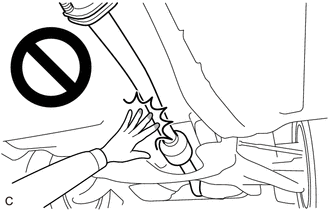
CAUTION:
To prevent burns, do not touch the engine, exhaust pipe or other high temperature components while the engine is hot.
PROCEDURE
1. REMOVE REAR WHEEL
Click here .gif)
2. REMOVE NO. 2 FLOOR UNDER COVER (for Gasoline Model)
| (a) Remove the 2 bolts and clip (A). |
|
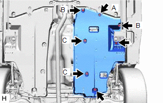
(b) Disengage the 2 grommets (B) and 2 clips (C) to remove the No. 2 floor under cover.
3. REMOVE NO. 1 FLOOR UNDER COVER (for Gasoline Model)
| (a) Remove the 2 bolts and clip (A). |
|
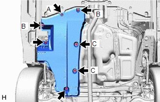
(b) Disengage the 2 grommets (B) and 2 clips (C) to remove the No. 1 floor under cover.
4. REMOVE CENTER EXHAUST PIPE ASSEMBLY
for 2GR-FKS: Click here
for A25A-FXS: Click here
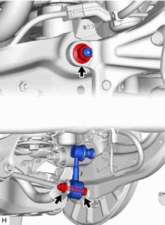
5. REMOVE REAR STABILIZER LINK ASSEMBLY LH
(a) Remove the cap from the rear stabilizer link assembly LH.
| (b) Loosen the nut (A) of the rear stabilizer link assembly LH. HINT: If the ball joint turns together with the nut, use a 6 mm hexagon socket wrench to hold the stud bolt. |
|
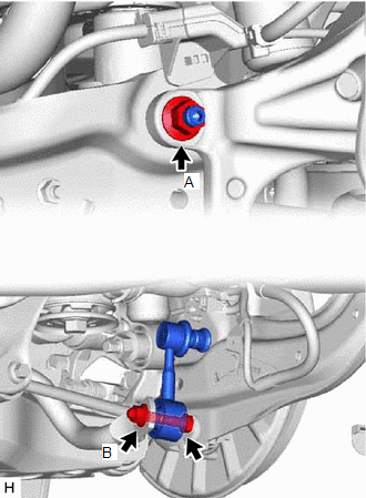
(c) Loosen the nut (B) of the rear stabilizer link assembly LH.
| (d) Using a jack and wooden block, support the rear No. 2 suspension arm assembly. NOTICE:
|
|
.png)
| (e) Remove the bolt, 2 nuts and rear stabilizer link assembly LH. |
|
6. REMOVE REAR STABILIZER LINK ASSEMBLY RH
HINT:
Perform the same procedure as for the LH side.
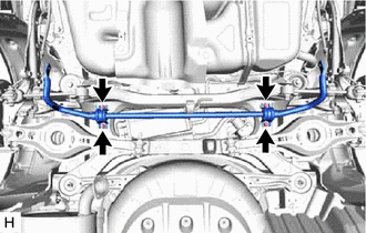
7. REMOVE REAR STABILIZER BAR
| (a) Remove the 4 bolts, rear stabilizer bar, 2 rear No. 1 stabilizer bar brackets and 2 rear stabilizer bushings from the rear suspension member sub-assembly. |
|
8. REMOVE REAR NO. 1 STABILIZER BAR BRACKET
| (a) Remove the 2 rear No. 1 stabilizer bar brackets from the 2 rear stabilizer bushings. |
|
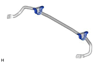
9. REMOVE REAR STABILIZER BUSHING
| (a) Remove the 2 rear stabilizer bushings from the rear stabilizer bar. |
|

READ NEXT:
 Inspection
INSPECTION PROCEDURE 1. INSPECT REAR STABILIZER LINK ASSEMBLY (a) Inspect the turning torque of the ball joint. (1) Secure the rear stabilizer link assembly in a vise using aluminum plates. NOTICE:
Installation
INSTALLATION PROCEDURE 1. INSTALL REAR STABILIZER BUSHING (a) Install the 2 rear stabilizer bushings to the rear stabilizer bar. NOTICE: Be sure to install the rear stabilizer bushings so that each cu
SEE MORE:
High Voltage Power Resource Circuit Consumption Circuit Short (P1C8149,P1C8249)
DTC SUMMARY MALFUNCTION DESCRIPTION The hybrid vehicle control ECU monitors the high-voltage wiring between the HV battery and inverter with converter assembly and detects a short circuit malfunction or high-voltage system operation malfunction. The cause of this malfunction may be one of the follow
Transmitter ID not Registered (Main) (C2171)
DESCRIPTION The IDs of each tire pressure warning valve and transmitter are registered to the tire pressure warning ECU and receiver. When the ECU detects that a transmitter ID code is not registered in the ECU, this DTC is stored. DTC No. Detection Item DTC Detection Condition Trouble Area
