Lexus ES: Removal
REMOVAL
CAUTION / NOTICE / HINT
The necessary procedures (adjustment, calibration, initialization or registration) that must be performed after parts are removed and installed, or replaced during camshaft timing gear bolt removal/installation are shown below.
Necessary Procedures After Parts Removed/Installed/Replaced| Replaced Part or Performed Procedure | Necessary Procedure | Effect/Inoperative Function when Necessary Procedure not Performed | Link |
|---|---|---|---|
| Battery terminal is disconnected/reconnected | Perform steering sensor zero point calibration | Lane Control System | |
| Pre-collision System | |||
| Parking Support Brake System*1 | |||
| Lighting System | |||
| Memorize steering angle neutral point | Parking Assist Monitor System | | |
| Panoramic View Monitor System | | ||
| Initialize power trunk lid system | Power Trunk Lid System | | |
| Replacement of ECM | Vehicle Identification Number (VIN) registration | MIL comes on | |
| ECU communication ID registration (Immobiliser system) | Engine start function | | |
| Gas leak from exhaust system is repaired | Inspection after repair |
| |
| Replacement of ECM (If transaxle compensation code read from ECM) |
|
| for Initialization: for Registration: |
| Replacement of ECM (If transaxle compensation code not read from ECM) |
| ||
| Replacement of ECM | Code registration (Smart access system with push-button start (for Start Function, Gasoline Model) |
| |
| Replacement of automatic transaxle fluid | ATF thermal degradation estimate reset | The value of the Data List item "ATF Thermal Degradation Estimate" is not estimated correctly | |
| Suspension, tires, etc. (The vehicle height changes because of suspension or tire replacement) | Rear television camera assembly optical axis adjustment (Back camera position setting) | Parking assist monitor system | for Initialization: for Calibration: |
| Perform headlight ECU sub-assembly LH initialization | Lighting system | | |
| Front wheel alignment adjustment |
|
| |
| Front television camera view adjustment | Panoramic View Monitor System | for Initialization for Calibration |
| Replacement of front bumper assembly |
|
| |
-
*1: When performing learning using the Techstream.
Click here
.gif)
- *2: Not necessary when ECM replaced with new one
NOTICE:
- After the engine switch is turned off, the radio receiver assembly records various types of memory and settings. As a result, after turning the engine switch off, make sure to wait at least 85 seconds before disconnecting the cable from the negative (-) battery terminal. (for Audio and Visual System)
- After the engine switch is turned off, the radio receiver assembly records various types of memory and settings. As a result, after turning the engine switch off, make sure to wait at least 85 seconds before disconnecting the cable from the negative (-) battery terminal. (for Navigation System)
PROCEDURE
1. REMOVE ENGINE ASSEMBLY WITH TRANSAXLE
Click here
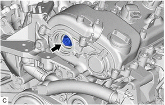
2. REMOVE CAMSHAFT TIMING OIL CONTROL SOLENOID ASSEMBLY (for Intake Side of Bank 2)
Click here
3. SET NO. 1 CYLINDER TO TDC/COMPRESSION
| (a) Turn the crankshaft pulley clockwise until its timing mark (cutout) is aligned with the timing mark on the timing chain cover assembly as shown in the illustration. |
|
.png)
(b) Check that the cutout of the camshaft timing gear assembly is at the top.
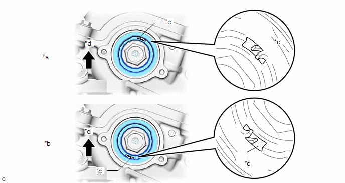
| *a | Correct | *b | Incorrect |
| *c | Cutout | *d | Up |
HINT:
If the cutout of the camshaft timing gear assembly is not at the top, turn the crankshaft 360° clockwise and align the timing mark (cutout) of the crankshaft pulley with the timing mark on the timing chain cover assembly again.
4. REMOVE CAMSHAFT TIMING GEAR BOLT
| (a) While holding the crankshaft pulley, remove the camshaft timing gear bolt. NOTICE:
|
|
READ NEXT:
 Inspection
INSPECTION PROCEDURE 1. INSPECT CAMSHAFT TIMING GEAR BOLT (a) Check the stroke of the plunger in the center of the camshaft timing gear bolt. Standard Stroke: 4.5 mm (0.177 in.) or more HINT: When
Installation
INSTALLATION PROCEDURE 1. INSTALL CAMSHAFT TIMING GEAR BOLT (a) Make sure that the No. 1 cylinder is at TDC/compression. HINT: Check that the cutout of the camshaft timing gear assembly is at the top
SEE MORE:
Open in Bus 4 Main Bus Line
DESCRIPTION There may be an open circuit in one of the CAN main bus lines when the resistance between terminals 22 (CA2H) and 7 (CA2L) of the central gateway ECU (network gateway ECU) is 70 Ω or higher. Symptom Trouble Area Resistance between terminals 22 (CA2H) and 7 (CA2L) of the central
(Extreme) Hybrid/EV Battery Stack 1 Cell Circuit Voltage Below Threshold (P33EC16,P33ED16)
DESCRIPTION If the voltage of an HV battery cell is lower than the threshold for a certain amount of time, the battery ECU assembly will interpret this as a malfunction. DTC No. Detection Item DTC Detection Condition Trouble Area MIL Warning Indicate P33EC16 (Extreme) Hybrid/EV Ba
