Lexus ES: Components
COMPONENTS
ILLUSTRATION
.png)
| *1 | FRONT FENDER APRON SEAL RH | *2 | V-BANK COVER SUB-ASSEMBLY |
.png) | N*m (kgf*cm, ft.*lbf): Specified torque | - | - |
ILLUSTRATION
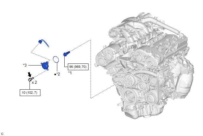
| *1 | CAMSHAFT TIMING GEAR BOLT | *2 | O-RING |
| *3 | CAMSHAFT TIMING OIL CONTROL SOLENOID ASSEMBLY (for Exhaust Side of Bank 2) | - | - |
| | N*m (kgf*cm, ft.*lbf): Specified torque | ● | Non-reusable part |
.png) | Adhesive 1324 | ★ | Precoated part |
READ NEXT:
 Removal
REMOVAL PROCEDURE 1. REMOVE FRONT WHEEL RH Click here 2. REMOVE FRONT FENDER APRON SEAL RH Click here 3. REMOVE V-BANK COVER SUB-ASSEMBLY Click here 4. REMOVE CAMSHAFT TIMING OIL CONTROL SOL
Inspection
INSPECTION PROCEDURE 1. INSPECT CAMSHAFT TIMING GEAR BOLT (a) Check the stroke of the plunger in the center of the camshaft timing gear bolt. Standard Stroke: 2.2 mm (0.0866 in.) or more HINT: Whe
Installation
INSTALLATION PROCEDURE 1. INSTALL CAMSHAFT TIMING GEAR BOLT (a) Make sure that the No. 1 cylinder is at TDC/compression. HINT: Check that the cutout of the camshaft timing gear assembly is at the top
SEE MORE:
Reassembly
REASSEMBLY CAUTION / NOTICE / HINT HINT:
Use the same procedure for the RH side and LH side.
The following procedure is for the LH side.
PROCEDURE 1. INSTALL HEADLIGHT SEAL (for TMC Made) HINT: Perform this procedure only when replacement of the headlight seal is necessary. (a) Clean the ins
On-vehicle Inspection
ON-VEHICLE INSPECTION PROCEDURE 1. INSPECT RADIO SETTING CONDENSER (a) With the radio setting condenser installed, check that there is no looseness or other abnormalities. (b) Measure the resistance of the radio setting condenser according to the value(s) in the table below. Standard Resistance:
© 2016-2026 Copyright www.lexguide.net
