Lexus ES: Components
COMPONENTS
ILLUSTRATION
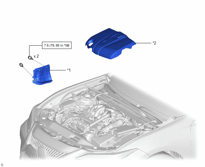
| *1 | FRONT FENDER APRON SEAL RH | *2 | V-BANK COVER SUB-ASSEMBLY |
.png) | N*m (kgf*cm, ft.*lbf): Specified torque | - | - |
ILLUSTRATION
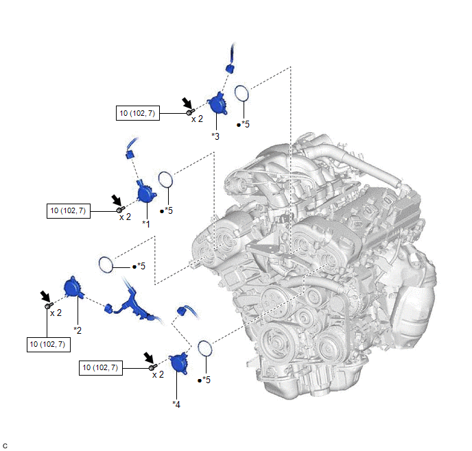
| *1 | CAMSHAFT TIMING OIL CONTROL SOLENOID ASSEMBLY (for Intake Side of Bank 1) | *2 | CAMSHAFT TIMING OIL CONTROL SOLENOID ASSEMBLY (for Exhaust Side of Bank 1) |
| *3 | CAMSHAFT TIMING OIL CONTROL SOLENOID ASSEMBLY (for Intake Side of Bank 2) | *4 | CAMSHAFT TIMING OIL CONTROL SOLENOID ASSEMBLY (for Exhaust Side of Bank 2) |
| *5 | O-RING | - | - |
| | N*m (kgf*cm, ft.*lbf): Specified torque | ● | Non-reusable part |
.png) | Adhesive 1324 | ★ | Precoated part |
READ NEXT:
 On-vehicle Inspection
ON-VEHICLE INSPECTION PROCEDURE 1. INSPECT CAMSHAFT TIMING OIL CONTROL SOLENOID ASSEMBLY (a) Connect the Techstream to the DLC3. (b) Start the engine. (c) Turn the Techstream on. (d) Inspect the camsh
Removal
REMOVAL CAUTION / NOTICE / HINT The necessary procedures (adjustment, calibration, initialization or registration) that must be performed after parts are removed and installed, or replaced during cams
Inspection
INSPECTION PROCEDURE 1. INSPECT CAMSHAFT TIMING OIL CONTROL SOLENOID ASSEMBLY HINT: Use the same procedure for the intake side and exhaust side. (a) Check the resistance. (1) Measure the resistance
SEE MORE:
Manifold Absolute Pressure / Barometric Pressure Sensor Signal Stuck in Range (P01052A)
DESCRIPTION Refer to DTC P010511. Click here DTC No. Detection Item DTC Detection Condition Trouble Area MIL Memory Note P01052A Manifold Absolute Pressure / Barometric Pressure Sensor Signal Stuck in Range Intake manifold pressure measured after engine start drops by less t
Check For Intermittent Problems
CHECK FOR INTERMITTENT PROBLEMS NOTICE:
If the vehicle or vehicle controls are operated (for example, during initial inspection when the vehicle is brought in for repair) before operation history has been read and saved, the operation history information could be lost.
The operation history fun
© 2016-2026 Copyright www.lexguide.net
