Lexus ES: Removal
REMOVAL
CAUTION / NOTICE / HINT
NOTICE:
Make sure to hold the front wiper arm while lifting it, as lifting the front wiper arm by the front wiper blade may damage or deform the front wiper blade.
PROCEDURE
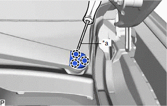
1. REMOVE FRONT WIPER ARM HEAD CAP
| (a) Using a screwdriver with its tip wrapped with protective tape, disengage the 3 claws to remove the front wiper arm head cap. HINT: Use the same procedure for the RH side and LH side. |
|
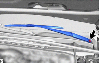
2. REMOVE FRONT WIPER ARM AND BLADE ASSEMBLY LH
| (a) Remove the nut and front wiper arm and blade assembly LH. |
|
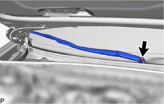
3. REMOVE FRONT WIPER ARM AND BLADE ASSEMBLY RH
| (a) Remove the nut and front wiper arm and blade assembly RH. |
|
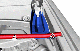
4. REMOVE NO. 3 COWL TOP PANEL INSULATOR
| (a) Disengage the 2 clips and disconnect the cowl top ventilator louver sub-assembly. |
|
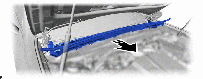
(b) Remove the clip.
.png) | Remove in this Direction |
(c) Disengage the 4 claws to remove the No. 3 cowl top panel insulator as shown in the illustration.
5. REMOVE NO. 2 COWL TOP PANEL INSULATOR
(a) Disengage the 2 clips and disconnect the cowl top ventilator louver sub-assembly.
(b) Remove the clip.
| | Remove in this Direction |
(c) Disengage the 4 claws to remove the No. 2 cowl top panel insulator as shown in the illustration.
6. DISCONNECT WINDSHIELD OUTSIDE MOULDING LH
| (a) Disengage the claw and separate the windshield outside moulding LH. |
|
7. DISCONNECT WINDSHIELD OUTSIDE MOULDING RH
| (a) Disengage the claw and separate the windshield outside moulding RH. |
|
8. REMOVE COWL TOP VENTILATOR LOUVER SUB-ASSEMBLY
NOTICE:
To prevent damage to the windshield glass, remove any foreign matter (sand, dust, etc.) from around the contacting surfaces of the cowl top ventilator louver sub-assembly and windshield glass.
(a) Close the hood sub-assembly.
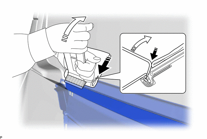
(b) Insert a moulding remover at the starting position, as far as it can be inserted, to lift the cowl top ventilator louver sub-assembly and then hold it as shown in the illustration.
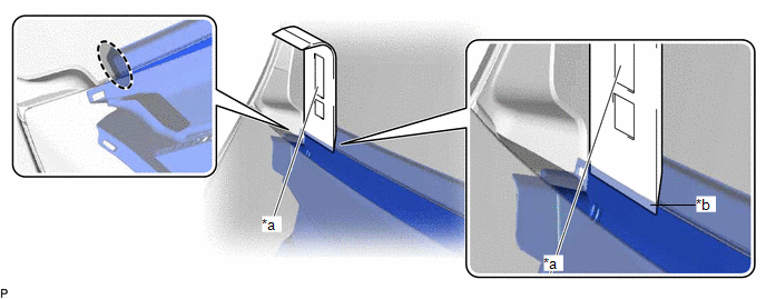
| *a | Starting Position: Side of Cowl Top Ventilator Louver Sub-assembly and Moulding Remover Aligned | *b | Inserted as Far as Possible |
.png) | Place Hand Here | - | - |
(c) Apply protective tape to a moulding remover as shown in the illustration.
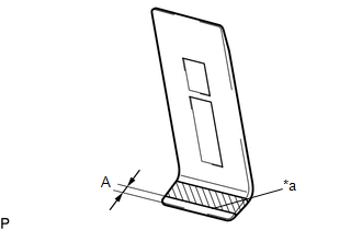
| *a | Edge of Protective Tape |
.png) | Protective Tape |
Standard Dimension:
| Area | Dimension |
|---|---|
| A | 4.0 mm (0.157 in.) |
(d) Insert the moulding remover at the starting position until the edge of the protective tape is aligned with the cowl top ventilator louver sub-assembly as shown in the illustration.
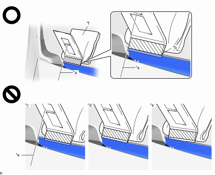
| *a | Starting Position: Side of Cowl Top Ventilator Louver Sub-assembly and Moulding Remover Aligned | *b | Inserted to Edge of Protective Tape |
| *c | Not Inserted at Starting Position | *d | Not Inserted to Edge of Protective Tape |
| *e | Not Inserted Straight | *f | Piece of Cloth or Equivalent |
| | Protective Tape | - | - |
NOTICE:
- To prevent damage to the windshield glass, set a piece of cloth between the moulding remover and windshield glass.
- Make sure to insert the moulding remover until the edge of protective tape is aligned with the cowl top ventilator louver sub-assembly, otherwise the cowl top ventilator louver sub-assembly may be deformed or damaged.
(e) While pushing the moulding remover in the direction indicated by the arrow (A), push the moulding remover in the direction indicated by the arrow (B) to disengage the cowl top ventilator louver sub-assembly.
| | Push in this Direction (A) | .png) | Push in this Direction (B) |
NOTICE:
- Make sure to repeat this procedure to disengage the entire cowl top ventilator louver sub-assembly.
- Make sure to perform this procedure while pushing the moulding remover in the direction indicated by the arrow (A), otherwise the cowl top ventilator louver sub-assembly may be deformed or damaged.
-
Make sure not to pry the cowl top ventilator louver sub-assembly more than necessary to disengage it, otherwise it may be deformed or damaged.
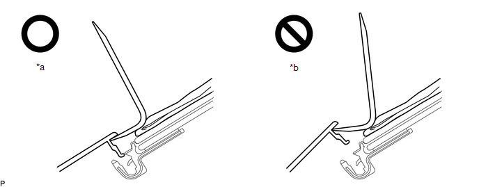
*a
Pried Until Disengaged
*b
Pried Excessively
(f) Using the moulding remover, repeatedly pry up the cowl top ventilator louver sub-assembly while gradually moving the moulding remover half of its width laterally toward the center of the vehicle and then repeat the procedure from the other side of the vehicle as shown in the illustration to disengage the cowl top ventilator louver sub-assembly from the windshield glass.
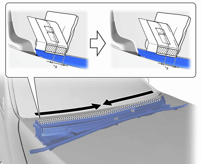
| *a | Half Width of Moulding Remover | - | - |
.png) | Order of Removal | - | - |
NOTICE:
- Make sure to move the moulding remover only half of its width laterally after prying up the cowl top ventilator louver sub-assembly, otherwise the cowl top ventilator louver sub-assembly may be damaged or deformed.
- Make sure not to lift up or pull the cowl top ventilator louver sub-assembly by hand before it is completely disengaged, otherwise it may be deformed or damaged.
(g) Open the hood sub-assembly.
(h) Disengage the 4 claws and guide as shown in the illustration.
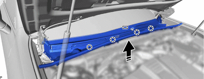
| | Remove in this Direction | - | - |
(i) Remove the cowl top ventilator louver sub-assembly as shown in the illustration.
| | Remove in this Direction | - | - |
9. REMOVE WINDSHIELD WIPER MOTOR AND LINK ASSEMBLY
| (a) Disengage the 2 clamps. |
|
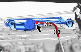
(b) Disconnect the connector.
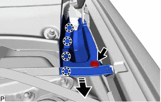
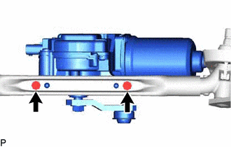
(c) Remove the bolt (A).
| *a | Motor Grommet |
| | Bolt (A) |
.png) | Bolt (B) |
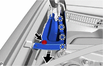
(d) Remove the bolt (B).
HINT:
Remove the bolt (B) and windshield wiper motor and link assembly as a set.
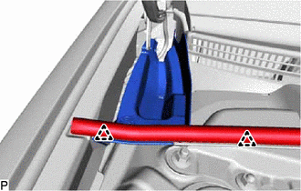
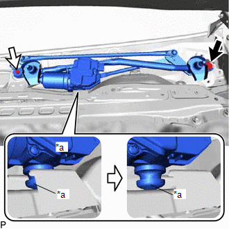
(e) Disengage the motor grommet as shown in the illustration.
(f) Remove the windshield wiper motor and link assembly as indicated by the arrows, in the order shown in the illustration.
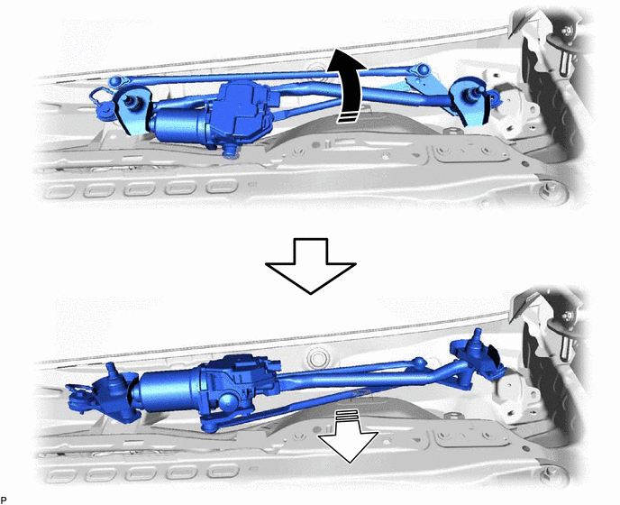
| | Remove in this Direction (1) | | Remove in this Direction (2) |
NOTICE:
Be careful not to damage the windshield glass when removing the windshield wiper motor and link assembly.
10. REMOVE WINDSHIELD WIPER MOTOR ASSEMBLY
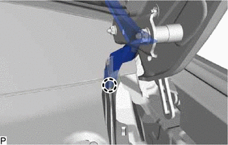
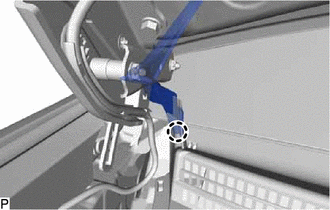
(a) Using a screwdriver with its tip wrapped with protective tape, separate the No. 1 wiper link rod from the pivot of the windshield wiper motor assembly as shown in the illustration.
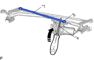
| *1 | No. 1 Wiper Link Rod |
| *a | Protective Tape |
| *b | Pivot of Windshield Wiper Motor Assembly |
| | Remove in this Direction |
| (b) Using a T30 "TORX" socket wrench, remove the 2 bolts and windshield wiper motor assembly from the wiper link assembly. |
|
READ NEXT:
 Inspection
INSPECTION CAUTION / NOTICE / HINT CAUTION: Be careful so that fingers and clothing do not get caught in the moving parts when performing this test. PROCEDURE 1. INSPECT WINDSHIELD WIPER MOTOR ASSEMBL
Installation
INSTALLATION CAUTION / NOTICE / HINT NOTICE: Make sure to hold the front wiper arm while lifting it, as lifting the front wiper arm by the front wiper blade may damage or deform the front wiper blade.
Front Wiper Rubber
ComponentsCOMPONENTS ILLUSTRATION *1 FRONT WIPER BLADE *2 WIPER RUBBER *3 FRONT WIPER RUBBER BACKING PLATE - - ReplacementREPLACEMENT CAUTION / NOTICE / HINT NOTICE: Make sure
SEE MORE:
Drive Motor "A" Position Sensor Circuit "A" Circuit Voltage Below Threshold (P0C5016,P0C5017,P0C5A16,P0C5A17)
DTC SUMMARY MALFUNCTION DESCRIPTION These DTCs indicate an abnormal resolver output signal. The cause of this malfunction may be one of the following: Internal inverter malfunction
Inverter with converter assembly internal circuit malfunction
Inverter low-voltage circuit malfunction
The con
Deceleration Sensor (C1232,C1243,C1245)
DESCRIPTION The airbag ECU assembly has a built-in yaw rate and acceleration sensor and detects the vehicle condition using 2 circuits (GL1, GL2). The skid control ECU (brake booster with master cylinder assembly) receives signals from the yaw rate and acceleration sensor (airbag ECU assembly) via t
