Lexus ES: Installation
INSTALLATION
PROCEDURE
1. INSTALL TRANSMISSION VALVE BODY ASSEMBLY
(a) Coat 2 new transaxle case gaskets with Toyota Genuine ATF WS and install them to the automatic transaxle case sub-assembly.
(b) Coat a new transaxle case gasket with Toyota Genuine ATF WS and install it to the counter drive gear sub-assembly.
(c) Coat a new No. 1 front oil pump cover gasket with Toyota Genuine ATF WS and install it to the front oil pump assembly.
(d) Coat a new No. 2 front oil pump cover gasket with Toyota Genuine ATF WS and install it to the front oil pump assembly.
| (e) Align the slit portion of the manual valve and the manual valve lever sub-assembly as shown in the illustration, and install the transmission valve body assembly to the automatic transaxle case sub-assembly with the 9 bolts. Torque: 10.8 N·m {110 kgf·cm, 8 ft·lbf} NOTICE: Be careful that the transmission revolution sensor (NC) wire is not pinched. |
|
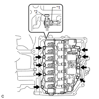
(f) Engage the clamp to connect the transmission revolution sensor (NC) wire connector.
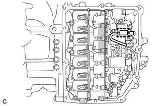
.png) | Do not let transmission revolution sensor (NC) wire ride up over this area. |
NOTICE:
To prevent it from being pinched between the transmission valve body assembly and the transmission case side cover, do not let the transmission revolution sensor (NC) wire ride up over the area shown in the illustration.
2. INSTALL TRANSMISSION WIRE
Click here .gif)
3. CHECK AUTOMATIC TRANSAXLE SYSTEM
NOTICE:
If automatic transaxle parts have been replaced, refer to Parts Replacement Compensation Table to determine if any additional operations are necessary.
Click here
READ NEXT:
 Reassembly
REASSEMBLY PROCEDURE 1. INSTALL SOLENOID (SL) VALVE (a) Coat the solenoid (SL) valve with Toyota Genuine ATF WS. (b) Install the solenoid (SL) valve to the transmission valve body assem
Removal
REMOVAL CAUTION / NOTICE / HINT The necessary procedures (adjustment, calibration, initialization or registration) that must be performed after parts are removed and installed, or replaced during tran
SEE MORE:
Removal
REMOVAL CAUTION / NOTICE / HINT The necessary procedures (adjustment, calibration, initialization, or registration) that must be performed after parts are removed and installed, or replaced during motor cable removal/installation are shown below. Necessary Procedure After Parts Removed/Installed/Rep
Removal
REMOVAL CAUTION / NOTICE / HINT HINT:
Use the same procedure for the RH side and LH side.
The following procedure is for the LH side.
PROCEDURE 1. REMOVE REAR POWER WINDOW REGULATOR SWITCH ASSEMBLY WITH REAR DOOR UPPER ARMREST BASE PANEL Click here 2. REMOVE REAR DOOR TRIM UPPER PAD Clic
