Lexus ES: Removal
REMOVAL
CAUTION / NOTICE / HINT
The necessary procedures (adjustment, calibration, initialization or registration) that must be performed after parts are removed and installed, or replaced during transmission valve body assembly removal/installation are shown below.
Necessary Procedures After Parts Removed/Installed/Replaced| Replaced Part or Performed Procedure | Necessary Procedure | Effect/Inoperative Function when Necessary Procedure not Performed | Link |
|---|---|---|---|
|
|
| |
| Replacement of automatic transaxle fluid | ATF thermal degradation estimate reset | The value of the Data List item "ATF Thermal Degradation Estimate" is not estimated correctly | |
PROCEDURE
1. REMOVE TRANSMISSION WIRE
Click here .gif)
2. REMOVE TRANSMISSION VALVE BODY ASSEMBLY
| (a) Disengage the clamp to disconnect the transmission revolution sensor (NC) wire connector. |
|
.png)
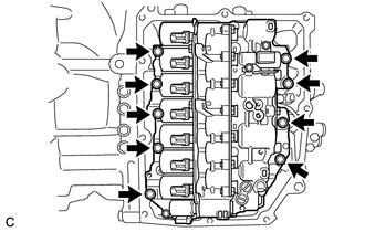
| (b) Remove the 9 bolts and transmission valve body assembly from the automatic transaxle case sub-assembly. |
|
| (c) Remove the 2 transaxle case gaskets from the automatic transaxle case sub-assembly. |
|

(d) Remove the transaxle case gasket from the counter drive gear sub-assembly.
(e) Remove the No. 1 front oil pump cover gasket from the front oil pump assembly.
(f) Remove the No. 2 front oil pump cover gasket from the front oil pump assembly.