Lexus ES: Installation
INSTALLATION
PROCEDURE
1. INSTALL TRANSMISSION OIL COOLER
| (a) Temporarily install the transmission oil cooler to the automatic transaxle case sub-assembly with the bolt (A). |
|
.png)
(b) Install the bolt (B).
Torque:
13.5 N·m {138 kgf·cm, 10 ft·lbf}
(c) Install the bolt (C).
Torque:
13.5 N·m {138 kgf·cm, 10 ft·lbf}
(d) Fully tighten the bolt (A) to install the transmission oil cooler.
Torque:
13.5 N·m {138 kgf·cm, 10 ft·lbf}
2. CONNECT WATER BY-PASS HOSE ASSEMBLY
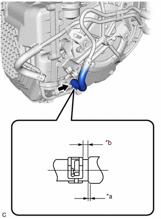
(a) Connect the water by-pass hose assembly to the transmission oil cooler and slide the clip to secure it.
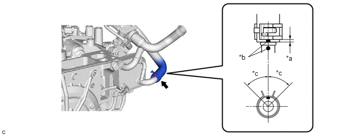
| *a | 2 to 7 mm (0.0787 to 0.276 in.) | *b | Paint Mark |
| *c | 45° (Claw of Clip Location) | - | - |
NOTICE:
- Make sure to slide the water by-pass hose assembly until it contacts the hose stopper of the transmission oil cooler.
- Make sure to align the paint mark of the water by-pass hose assembly with the paint mark of the transmission oil cooler.
- Make sure that the claws of the clip are within the location shown in the illustration.
3. CONNECT NO. 1 WATER BY-PASS HOSE
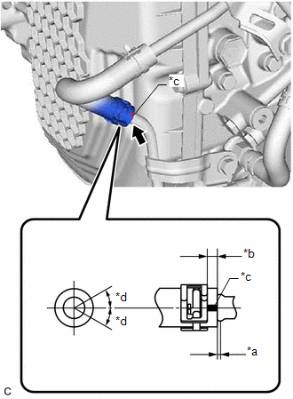
(a) Connect the No. 1 water by-pass hose to the transmission oil cooler and slide the clip to secure it.
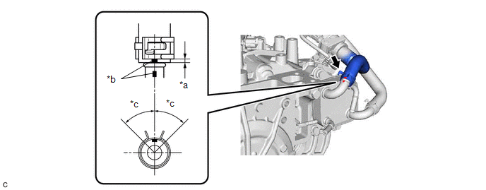
| *a | 2 to 7 mm (0.0787 to 0.276 in.) | *b | Paint Mark |
| *c | 45° (Claw of Clip Location) | - | - |
NOTICE:
- Make sure to slide the No. 1 water by-pass hose until it contacts the hose stopper of the transmission oil cooler.
- Make sure to align the paint mark of the No. 1 water by-pass hose with the paint mark of the transmission oil cooler.
- Make sure that the claws of the clip are within the location shown in the illustration.
(b) Engage the 3 clamps to install the transmission breather clamp.
4. INSTALL NO. 1 OIL COOLER TUBE SUB-ASSEMBLY WITHOUT HOSE
(a) Install the inlet No. 1 oil cooler hose, inlet No. 2 oil cooler hose, outlet No. 1 oil cooler hose and outlet No. 2 oil cooler hose to the No. 1 oil cooler tube sub-assembly without hose and slide the 4 clips to secure them.
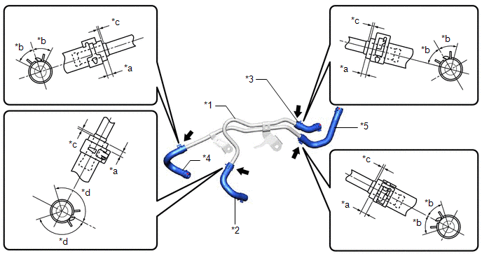
| *1 | No. 1 Oil Cooler Tube Sub-assembly without Hose | *2 | Inlet No. 1 Oil Cooler Hose |
| *3 | Inlet No. 2 Oil Cooler Hose | *4 | Outlet No. 1 Oil Cooler Hose |
| *5 | Outlet No. 2 Oil Cooler Hose | - | - |
| *a | 2 to 7 mm (0.0787 to 0.276 in.) | *b | 45° (Claw of Clip Location) |
| *c | 0 to 3 mm (0 to 0.118 in.) | *d | 135° (Claw of Clip Location) |
NOTICE:
- Make sure to slide the inlet No. 1 oil cooler hose, inlet No. 2 oil cooler hose, outlet No. 1 oil cooler hose and outlet No. 2 oil cooler hose until each contacts the hose stopper of the No. 1 oil cooler tube sub-assembly without hose.
- Make sure that the claws of each clip are within the location shown in the illustration.
| (b) Connect the outlet No. 2 oil cooler hose to the transmission oil cooler and slide the clip to secure it. NOTICE:
|
|
.png)
| (c) Connect the inlet No. 2 oil cooler hose to the transmission oil cooler and slide the clip to secure it. NOTICE:
|
|
.png)
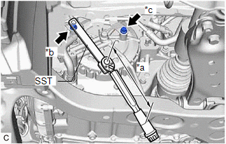
(d) Temporarily install the No. 1 oil cooler tube sub-assembly without hose to the automatic transaxle case sub-assembly with the 2 bolts.
| (e) Using SST, tighten the bolt (A). SST: 09961-00950 Torque: Specified tightening torque : 13.5 N·m {138 kgf·cm, 10 ft·lbf} HINT:
|
|
(f) Tighten the bolt (B).
Torque:
13.5 N·m {138 kgf·cm, 10 ft·lbf}
5. CONNECT INLET NO. 1 OIL COOLER HOSE
| (a) Connect the inlet No. 1 oil cooler hose to the No. 1 oil cooler outlet tube sub-assembly and slide the clip to secure it. NOTICE: Make sure to slide the inlet No. 1 oil cooler hose until it contacts the hose stopper of the No. 1 oil cooler outlet tube sub-assembly. |
|
6. CONNECT OUTLET NO. 1 OIL COOLER HOSE
| (a) Connect the outlet No. 1 oil cooler hose to the oil cooler union sub-assembly and slide the clip to secure it. NOTICE:
|
|
7. INSTALL BATTERY CLAMP SUB-ASSEMBLY
Click here .gif)
8. INSTALL ECM
Click here
9. INSTALL BATTERY
Click here
10. ADD ENGINE COOLANT
Click here
11. ADJUST AUTOMATIC TRANSAXLE FLUID
Click here
12. INSPECT FOR AUTOMATIC TRANSAXLE FLUID LEAK
13. INSPECT FOR COOLANT LEAK
Click here
14. INSTALL FRONT FENDER APRON SEAL LH
Click here
15. INSTALL NO. 2 ENGINE UNDER COVER ASSEMBLY
Click here
16. INSTALL NO. 1 ENGINE UNDER COVER
Click here
17. INSTALL FRONT WHEEL OPENING EXTENSION PAD LH
Click here
18. INSTALL FRONT WHEEL OPENING EXTENSION PAD RH
Click here
19. INSTALL FRONT WHEEL LH
Click here
READ NEXT:
 Components
COMPONENTS ILLUSTRATION *1 CLUTCH DRUM OIL SEAL RING *2 FRONT OIL PUMP BODY *3 FRONT OIL PUMP DRIVE GEAR *4 FRONT OIL PUMP DRIVEN GEAR *5 OIL STRAINER ASSEMBLY *6 RING PI
Disassembly
DISASSEMBLY PROCEDURE 1. REMOVE CLUTCH DRUM OIL SEAL RING (a) Remove the 4 clutch drum oil seal rings from the stator shaft assembly. NOTICE: Do not expand the gap of the clutch drum oil seal rings
SEE MORE:
No. 1 Clearance Warning Buzzer Circuit
DESCRIPTION This circuit consists of the No. 1 clearance warning buzzer and clearance warning ECU assembly. An ECU-excited type buzzer is used. The ECU operates the buzzers using a sound pattern that changes depending on the distance to the obstacle. WIRING DIAGRAM PROCEDURE 1. PERFORM ACTIVE
Disassembly
DISASSEMBLY PROCEDURE 1. REMOVE MANUAL VALVE (a) Remove the manual valve from the transmission valve body assembly. 2. REMOVE SOLENOID LOCK PLATE (a) Remove the 3 bolts and solenoid lock plate from the transmission valve body assembly. 3. REMOVE SOLENOID (SLU) VALVE
