Lexus ES: No. 1 Clearance Warning Buzzer Circuit
DESCRIPTION
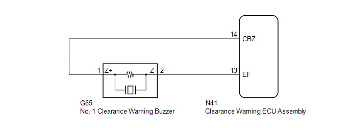
This circuit consists of the No. 1 clearance warning buzzer and clearance warning ECU assembly. An ECU-excited type buzzer is used. The ECU operates the buzzers using a sound pattern that changes depending on the distance to the obstacle.
WIRING DIAGRAM
PROCEDURE
| 1. | PERFORM ACTIVE TEST USING TECHSTREAM |
(a) Connect the Techstream to the DLC3.
(b) Turn the power switch on (IG).
(c) Turn the Techstream on.
(d) Enter the following menus: Body Electrical / Advanced Parking Guidance/ICS/Intuitive P/A / Active Test.
(e) Check that the buzzer operates by performing the Active Test.
Body Electrical > Advanced Parking Guidance/ICS/Intuitive P/A > Active Test| Tester Display | Measurement Item | Control Range | Diagnostic Note |
|---|---|---|---|
| Buzzer | No. 1 clearance warning buzzer | Operate or Stop | Confirm that the vehicle is stopped and the power switch is on (IG) |
| Tester Display |
|---|
| Buzzer |
OK:
The No. 1 clearance warning buzzer sounds.
| OK | .gif) | REPLACE CLEARANCE WARNING ECU ASSEMBLY |
|
.gif)
| 2. | CHECK HARNESS AND CONNECTOR (CLEARANCE WARNING ECU ASSEMBLY - NO. 1 CLEARANCE WARNING BUZZER) |
(a) Disconnect the N41 clearance warning ECU assembly connector.
(b) Disconnect the G65 No. 1 clearance warning buzzer connector.
(c) Measure the resistance according to the value(s) in the table below.
Standard Resistance:
| Tester Connection | Condition | Specified Condition |
|---|---|---|
| N41-14 (CBZ) - G65-1 (Z+) | Always | Below 1 Ω |
| N41-13 (EF) - G65-2 (Z-) | Always | Below 1 Ω |
| N41-14 (CBZ) or G65-1 (Z+) - Body ground | Always | 10 kΩ or higher |
| N41-13 (EF) or G65-2 (Z-) - Body ground | Always | 10 kΩ or higher |
| NG | | REPAIR OR REPLACE HARNESS OR CONNECTOR |
|
| 3. | REPLACE NO. 1 CLEARANCE WARNING BUZZER |
(a) Replace the No. 1 clearance warning buzzer with a new or known good one.
Click here .gif)
|
| 4. | PERFORM ACTIVE TEST USING TECHSTREAM |
(a) Connect the Techstream to the DLC3.
(b) Turn the power switch on (IG).
(c) Turn the Techstream on.
(d) Enter the following menus: Body Electrical / Advanced Parking Guidance/ICS/Intuitive P/A / Active Test.
(e) Check that the buzzer operates by performing the Active Test.
Body Electrical > Advanced Parking Guidance/ICS/Intuitive P/A > Active Test| Tester Display | Measurement Item | Control Range | Diagnostic Note |
|---|---|---|---|
| Buzzer | No. 1 clearance warning buzzer | Operate or Stop | Confirm that the vehicle is stopped and the power switch is on (IG) |
| Tester Display |
|---|
| Buzzer |
OK:
The No. 1 clearance warning buzzer sounds.
| OK | | END |
| NG | | REPLACE CLEARANCE WARNING ECU ASSEMBLY |
READ NEXT:
 No. 2 Clearance Warning Buzzer Circuit
DESCRIPTION This circuit consists of the No. 2 clearance warning buzzer and clearance warning ECU assembly. An ECU-excited type buzzer is used. The ECU operates the buzzers using a sound pattern that
Operation Check
OPERATION CHECK SELF-DIAGNOSIS SYSTEM (a) When a malfunction occurs in the parking support alert system or the system cannot be used, a warning is displayed on the multi-information display, each indi
Parts Location
PARTS LOCATION ILLUSTRATION *1 FRONT CORNER ULTRASONIC SENSOR RH *2 FRONT CENTER ULTRASONIC SENSOR RH *3 FRONT CENTER ULTRASONIC SENSOR LH *4 FRONT CORNER ULTRASONIC SENSOR LH
SEE MORE:
Transmission Fluid Temperature Sensor "A" Circuit Short To Ground (P071011)
DESCRIPTION The ATF temperature sensor converts the automatic transaxle fluid (ATF) temperature into a resistance value for use by the ECM. The ECM applies voltage to the temperature sensor through terminal THO1 of the ECM. The sensor resistance changes with the ATF temperature. As the temperature r
Vehicle Information Unmatched (C168D)
DESCRIPTION This DTC is stored if the rear television camera assembly judges as a result of its self check that the vehicle information received from the main body ECU (multiplex network body ECU) via CAN communication and the vehicle information stored in the rear television camera assembly do not
