Lexus ES: Installation
INSTALLATION
CAUTION / NOTICE / HINT
for HV Model:- When removing or installing the rear disc brake caliper assembly, pushing back the disc brake piston may cause a large clearance between the brake pads and brake disc. When the brake pedal is depressed with a large clearance between the brake pads and the brake disc, DTC C1214 related to abnormal brake fluid pressure may be stored. Make sure to clear any DTCs after performing this procedure.
- While the auxiliary battery is connected, even if the power switch is off, the brake control system activates when the brake pedal is depressed or any door courtesy switch turns on. Therefore, when servicing the brake system components, do not operate the brake pedal or open/close the doors while the auxiliary battery is connected.
HINT:
- Use the same procedure for the RH side and LH side.
- The following procedure is for the LH side.
PROCEDURE
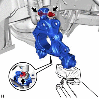
1. TEMPORARILY INSTALL REAR AXLE CARRIER SUB-ASSEMBLY
(a) Temporarily install the rear axle carrier sub-assembly to the rear shock absorber assembly with the nut and plate washer.
NOTICE:
Hold the rear axle carrier pin while rotating the nut.
| (b) Temporarily install the rear axle carrier sub-assembly to the rear upper control arm assembly with the bolt and nut. NOTICE:
|
|
(c) Install the rear trailing arm assembly to the rear axle carrier sub-assembly with the 2 bolts.
Torque:
135 N·m {1377 kgf·cm, 100 ft·lbf}
2. INSTALL REAR FLEXIBLE HOSE BRACKET
(a) Install the rear flexible hose bracket to the rear axle carrier sub-assembly with the bolt.
Torque:
29 N·m {296 kgf·cm, 21 ft·lbf}
3. TEMPORARILY INSTALL REAR NO. 1 SUSPENSION ARM ASSEMBLY
Click here .gif)
4. INSTALL REAR LOWER COIL SPRING INSULATOR
Click here
5. INSTALL REAR COIL SPRING
Click here
6. STABILIZE SUSPENSION
Click here
7. INSTALL REAR UPPER CONTROL ARM ASSEMBLY
(a) Install the rear upper control arm assembly to the rear axle carrier sub-assembly with the bolt.
Torque:
73 N·m {744 kgf·cm, 54 ft·lbf}
NOTICE:
Because the nut has its own stopper, do not turn the nut. Tighten the bolt with the nut secured.
8. INSTALL REAR NO. 1 SUSPENSION ARM ASSEMBLY
Click here
9. INSTALL REAR NO. 2 SUSPENSION ARM ASSEMBLY
(a) Install the rear No. 2 suspension arm assembly (rear axle carrier sub-assembly side) with the bolt.
Click here
10. INSTALL REAR SHOCK ABSORBER ASSEMBLY
Click here
11. INSTALL REAR STABILIZER LINK ASSEMBLY
Click here
12. INSTALL REAR AXLE HUB AND BEARING ASSEMBLY
Click here
13. INSTALL REAR DISC
Click here
14. INSTALL REAR DISC BRAKE CALIPER ASSEMBLY
Click here
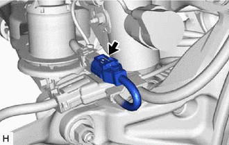
15. INSTALL REAR FLEXIBLE HOSE
(a) Install the rear flexible hose to the rear flexible hose bracket.
Torque:
29 N·m {296 kgf·cm, 21 ft·lbf}
16. INSTALL NO. 2 PARKING BRAKE WIRE ASSEMBLY (w/o AVS)
| (a) Install the No. 2 parking brake wire assembly to the rear trailing arm assembly with the nut. Torque: 15.5 N·m {158 kgf·cm, 11 ft·lbf} |
|
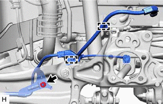
(b) Engage the 2 clamps.
(c) Connect the No. 2 parking brake wire assembly connector to the parking brake actuator assembly.
(d) Connect the No. 2 parking brake wire assembly connector to the rear axle hub and bearing assembly.
17. INSTALL NO. 2 PARKING BRAKE WIRE ASSEMBLY (w/ AVS)
| (a) Install the No. 2 parking brake wire assembly to the rear trailing arm assembly with the nut. Torque: 15.5 N·m {158 kgf·cm, 11 ft·lbf} |
|
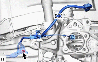
(b) Engage the clamp.
| (c) Engage the guide and install the wire harness bracket. |
|
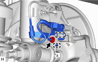
(d) Install the nut.
Torque:
8.5 N·m {87 kgf·cm, 75 in·lbf}
(e) Engage the clamp and install the No. 2 parking brake wire assembly to the wire harness bracket.
| (f) Connect the connector. |
|
(g) Connect the No. 2 parking brake wire assembly connector to the parking brake actuator assembly.
(h) Connect the No. 2 parking brake wire assembly connector to the rear axle hub and bearing assembly.
18. INSTALL NO. 1 FLOOR UNDER COVER (for Gasoline Model)
(a) for RH Side:
Click here
19. INSTALL NO. 2 FLOOR UNDER COVER (for Gasoline Model)
(a) for LH Side:
Click here
20. INSTALL REAR HEIGHT CONTROL SENSOR SUB-ASSEMBLY LH (w/ Height Control Sensor)
(a) for LH Side:
Click here
21. INSTALL REAR WHEEL
Click here
22. INSTALL REAR NO. 2 SUSPENSION ARM ASSEMBLY
(a) Install the rear No. 2 suspension arm assembly (rear suspension member sub-assembly side) with the nut.
Click here
23. CONNECT CABLE TO NEGATIVE AUXILIARY BATTERY TERMINAL (for HV Model)
(a) Connect the reservoir level switch connector.
(b) Connect the cable to the negative (-) auxiliary battery terminal.
Click here
(c) Turn the power switch on (READY).
(d) Depress the brake pedal and release it.
(e) Clear the DTCs.
Click here
24. INSPECT AND ADJUST REAR WHEEL ALIGNMENT
Click here
25. CHECK FOR SPEED SENSOR SIGNAL
for HV Model: Click here
for Gasoline Model: Click here
26. PERFORM INITIALIZATION
for HV Model:| *1: for LED type turn signal light | |
| |
| Parking Assist Monitor System | |
| Panoramic View Monitor System | |
| Lighting System*1 | |
| *1: for LED type turn signal light | |
| |
| Parking Assist Monitor System | |
| Panoramic View Monitor System | |
| Lighting System*1 | |
READ NEXT:
 Removal
REMOVAL CAUTION / NOTICE / HINT The necessary procedures (adjustment, calibration, initialization, or registration) that must be performed after parts are removed and installed, or replaced during rea
Components
COMPONENTS ILLUSTRATION *1 NO. 2 PARKING BRAKE WIRE ASSEMBLY *2 REAR AXLE HUB AND BEARING ASSEMBLY *3 REAR AXLE SHAFT NUT *4 REAR DISC *5 REAR DISC BRAKE CALIPER ASSEMBLY *
SEE MORE:
If a warning light turns on or a
warning buzzer sounds
Calmly perform the following actions if any of the warning lights comes
on or
flashes. If a light comes on or flashes, but then goes off, this does not
necessarily
indicate a malfunction in the system. However, if this continues to occur,
have the vehicle inspected by your Lexus dealer.
Acti
Installation
INSTALLATION PROCEDURE 1. INSTALL AIR FUEL RATIO SENSOR HINT: Perform "Inspection After Repair" after replacing the air fuel ratio sensor. Click here (a) Using SST, install the air fuel ratio sensor to the front exhaust pipe assembly (TWC: Rear Catalyst). SST: 09224-00012 Torque: Specified
