Lexus ES: Lost Communication with Image Processing Sensor B (U0266-U0268)
DESCRIPTION
These DTCs are stored when communication between the parking assist ECU and front television camera assembly, side television camera assembly LH, side television camera RH is not possible.
| DTC No. | Detection Item | DTC Detection Condition | Trouble Area |
|---|---|---|---|
| U0266 | Lost Communication with Image Processing Sensor B | Lost Communication with side television camera assembly LH | CAN communication system |
| U0267 | Lost Communication with Image Processing Sensor C | Lost Communication with front television camera assembly | CAN communication system |
| U0268 | Lost Communication with Image Processing Sensor D | Lost Communication with side television camera assembly RH | CAN communication system |
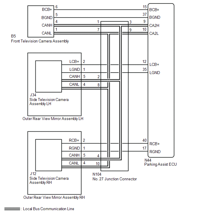
WIRING DIAGRAM
CAUTION / NOTICE / HINT
NOTICE:
-
After turning the engine switch off, waiting time may be required before disconnecting the cable from the negative (-) auxiliary battery terminal. Therefore, make sure to read the disconnecting the cable from the negative (-) auxiliary battery terminal notices before proceeding with work.
Click here
.gif)
- Inspect the fuses for circuits related to this system before performing the following procedure.
PROCEDURE
| 1. | CHECK DTC |
(a) Clear the DTCs.
Chassis > Circumference Monitoring Camera Control Module > Clear DTCs(b) Recheck for DTCs and check that no DTCs are output.
Chassis > Circumference Monitoring Camera Control Module > Trouble Codes| Result | Proceed to |
|---|---|
| All DTCs are not output | A |
| All DTCs are output | B |
| DTC U0266 is output | C |
| DTC U0267 is output | D |
| DTCs U0268 is output | E |
| A |  | USE SIMULATION METHOD TO CHECK |
| C | | GO TO STEP 9 |
| D | | GO TO STEP 10 |
| E | | GO TO STEP 11 |
|

| 2. | CHECK LOCAL BUS |
(a) Disconnect the cable from the negative (-) auxiliary battery terminal.
(b) Measure the resistance according to the value(s) in the table below.
Standard Resistance:
| Tester Connection | Condition | Specified Condition |
|---|---|---|
| N104-3 - N104-9 | Cable disconnected from negative (-) auxiliary battery terminal | 54 to 69 Ω |
| Result | Proceed to |
|---|---|
| OK | A |
| NG (Below 54 Ω) | B |
| NG (70 Ω or higher) | C |
| A | | USE SIMULATION METHOD TO CHECK |
| C | | GO TO STEP 7 |
|
| 3. | CHECK HARNESS AND CONNECTOR (PARKING ASSIST ECU - NO. 27 JUNCTION CONNECTOR) |
(a) Disconnect the cable from the negative (-) auxiliary battery terminal.
(b) Disconnect the N104 No. 27 junction connector.
(c) Connect the N44 parking assist ECU connector.
(d) Measure the resistance according to the value(s) in the table below.
Standard Resistance:
| Tester Connection | Condition | Specified Condition |
|---|---|---|
| N104-3 - N104-9 | Cable disconnected from negative (-) auxiliary battery terminal | 108 to 132 Ω |
| NG | | REPLACE PARKING ASSIST ECU |
|
| 4. | CHECK HARNESS AND CONNECTOR (SIDE TELEVISION CAMERA ASSEMBLY LH - NO. 27 JUNCTION CONNECTOR) |
(a) Disconnect the cable from the negative (-) auxiliary battery terminal.
(b) Disconnect the N104 No. 27 junction connector.
(c) Connect the J34 side television camera assembly LH connector.
(d) Measure the resistance according to the value(s) in the table below.
Standard Resistance:
| Tester Connection | Condition | Specified Condition |
|---|---|---|
| N104-2 - N104-8 | Cable disconnected from negative (-) auxiliary battery terminal | 108 to 132 Ω |
| NG | | REPLACE SIDE TELEVISION CAMERA ASSEMBLY LH |
|
| 5. | CHECK HARNESS AND CONNECTOR (FRONT TELEVISION CAMERA ASSEMBLY - NO. 27 JUNCTION CONNECTOR) |
(a) Disconnect the cable from the negative (-) auxiliary battery terminal.
(b) Disconnect the N104 No. 27 junction connector.
(c) Connect the B5 front television camera assembly connector.
(d) Measure the resistance according to the value(s) in the table below.
Standard Resistance:
| Tester Connection | Condition | Specified Condition |
|---|---|---|
| N104-1 - N104-7 | Cable disconnected from negative (-) auxiliary battery terminal | 200 Ω or higher |
| NG | | REPLACE FRONT TELEVISION CAMERA ASSEMBLY |
|
| 6. | CHECK HARNESS AND CONNECTOR (SIDE TELEVISION CAMERA ASSEMBLY RH - NO. 27 JUNCTION CONNECTOR) |
(a) Disconnect the cable from the negative (-) auxiliary battery terminal.
(b) Disconnect the N104 No. 27 junction connector.
(c) Connect the J12 side television camera assembly RH connector.
(d) Measure the resistance according to the value(s) in the table below.
Standard Resistance:
| Tester Connection | Condition | Specified Condition |
|---|---|---|
| N104-4 - N104-10 | Cable disconnected from negative (-) auxiliary battery terminal | 200 Ω or higher |
| OK | | REPLACE NO. 27 JUNCTION CONNECTOR |
| NG | | REPLACE SIDE TELEVISION CAMERA ASSEMBLY RH |
| 7. | CHECK HARNESS AND CONNECTOR (PARKING ASSIST ECU - NO. 27 JUNCTION CONNECTOR) |
(a) Disconnect the cable from the negative (-) auxiliary battery terminal.
(b) Disconnect the N104 No. 27 junction connector.
(c) Connect the N44 parking assist ECU connector.
(d) Measure the resistance according to the value(s) in the table below.
Standard Resistance:
| Tester Connection | Condition | Specified Condition |
|---|---|---|
| N44-9 (CA2H) - N44-10 (CA2L) | Cable disconnected from negative (-) auxiliary battery terminal | 108 to 132 Ω |
| OK | | REPLACE PARKING ASSIST ECU |
|
| 8. | CHECK HARNESS AND CONNECTOR (PARKING ASSIST ECU - NO. 27 JUNCTION CONNECTOR) |
(a) Disconnect the cable from the negative (-) auxiliary battery terminal.
(b) Disconnect the N104 No. 27 junction connector.
(c) Connect the N44 parking assist ECU connector.
(d) Measure the resistance according to the value(s) in the table below.
Standard Resistance:
| Tester Connection | Condition | Specified Condition |
|---|---|---|
| N104-3 - N104-9 | Cable disconnected from negative (-) auxiliary battery terminal | 108 to 132 Ω |
| OK | | REPLACE NO. 27 JUNCTION CONNECTOR |
| NG | | REPAIR OR REPLACE HARNESS OR CONNECTOR |
| 9. | CHECK HARNESS AND CONNECTOR (SIDE TELEVISION CAMERA ASSEMBLY LH - NO. 27 JUNCTION CONNECTOR) |
(a) Disconnect the cable from the negative (-) auxiliary battery terminal.
(b) Disconnect the J34 side television camera assembly LH connector.
(c) Measure the resistance according to the value(s) in the table below.
Standard Resistance:
| Tester Connection | Condition | Specified Condition |
|---|---|---|
| J34-5 (CANH) - J34-4 (CANL) | Cable disconnected from negative (-) auxiliary battery terminal | 108 to 132 Ω |
| OK | | REPLACE SIDE TELEVISION CAMERA ASSEMBLY LH |
| NG | | REPAIR OR REPLACE HARNESS OR CONNECTOR |
| 10. | CHECK HARNESS AND CONNECTOR (FRONT TELEVISION CAMERA ASSEMBLY - NO. 27 JUNCTION CONNECTOR) |
(a) Disconnect the cable from the negative (-) auxiliary battery terminal.
(b) Disconnect the B5 front television camera assembly connector.
(c) Measure the resistance according to the value(s) in the table below.
Standard Resistance:
| Tester Connection | Condition | Specified Condition |
|---|---|---|
| B5-4 (CANH) - B5-1 (CANL) | Cable disconnected from negative (-) auxiliary battery terminal | 108 to 132 Ω |
| OK | | REPLACE FRONT TELEVISION CAMERA ASSEMBLY |
| NG | | REPAIR OR REPLACE HARNESS OR CONNECTOR |
| 11. | CHECK HARNESS AND CONNECTOR (SIDE TELEVISION CAMERA ASSEMBLY RH - NO. 27 JUNCTION CONNECTOR) |
(a) Disconnect the cable from the negative (-) auxiliary battery terminal.
(b) Disconnect the J12 side television camera assembly RH connector.
(c) Measure the resistance according to the value(s) in the table below.
Standard Resistance:
| Tester Connection | Condition | Specified Condition |
|---|---|---|
| J12-5 (CANH) - J12-4 (CANL) | Cable disconnected from negative (-) auxiliary battery terminal | 108 to 132 Ω |
| OK | | REPLACE SIDE TELEVISION CAMERA ASSEMBLY RH |
| NG | | REPAIR OR REPLACE HARNESS OR CONNECTOR |
READ NEXT:
 CAN Communication Failure (Message Registry) (U1000)
DESCRIPTION If DTC U1000 is stored frequently, duplicate the problem symptoms and perform troubleshooting again even if the DTC is not output when rechecking for DTCs. DTC No. Detection Item DT
Components
COMPONENTS ILLUSTRATION *1 PARKING ASSIST ECU *2 PARKING ASSIST ECU COVER
SEE MORE:
Navigation Processor Malfunction (B15AD)
DESCRIPTION This DTC is stored when a malfunction occurs in the navigation ECU. DTC No. Detection Item DTC Detection Condition Trouble Area B15AD Navigation Processor Malfunction When either condition below is met:
A short to ground, short to +B or open occurs in the gyro signal
Generator Execution Torque Performance (P0E7100)
DTC SUMMARY MALFUNCTION DESCRIPTION This DTC indicates that the generator torque execution value does not correspond to the torque command value from the hybrid vehicle control ECU to the generator (MG1). The cause of this malfunction may be one of the following: Area Main Malfunction Descripti
