Lexus ES: Removal
REMOVAL
CAUTION / NOTICE / HINT
The necessary procedures (adjustment, calibration, initialization, or registration) that must be performed after parts are removed and installed, or replaced during rear axle carrier sub-assembly removal/installation are shown below.
Necessary Procedures After Parts Removed/Installed/Replaced (for HV Model:)| Replaced Part or Performed Procedure | Necessary Procedure | Effect/Inoperative Function when Necessary Procedure not Performed | Link |
|---|---|---|---|
|
*1: When performing learning using the Techstream.
Click here *2: for LED type turn signal light | |||
| Auxiliary battery terminal is disconnected/reconnected | Perform steering sensor zero point calibration | Lane Control System | |
| Pre-collision System | |||
| Parking Support Brake System*1 | |||
| Lighting System | |||
| Memorize steering angle neutral point | Parking Assist Monitor System | | |
| Panoramic View Monitor System | | ||
| Initialize power trunk lid system | Power Trunk Lid System | | |
| Suspension, tires, etc. (The vehicle height changes because of suspension or tire replacement.) |
|
| |
| Rear television camera assembly optical axis adjustment (Back camera position setting) | Parking Assist Monitor System | | |
| Panoramic View Monitor System | | |
| Perform headlight ECU sub-assembly LH initialization*2 | Lighting System | | |
| Rear height control sensor sub-assembly LH | Perform headlight ECU sub-assembly LH initialization*2 | Lighting System | |
| Rear wheel alignment adjustment |
|
| |
| Replaced Part or Performed Procedure | Necessary Procedure | Effect/Inoperative Function when Necessary Procedure not Performed | Link |
|---|---|---|---|
| *1: for LED Type Turn Signal Light | |||
| Suspension, tires, etc. (The vehicle height changes because of suspension or tire replacement.) |
|
| |
| Rear television camera assembly optical axis adjustment (Back camera position setting) | Parking Assist Monitor System | | |
| Panoramic View Monitor System | | |
| Perform headlight ECU sub-assembly LH initialization*1 | Lighting System | | |
| Rear height control sensor sub-assembly LH | Perform headlight ECU sub-assembly LH initialization*1 | Lighting System | |
| Rear wheel alignment adjustment |
|
| |
NOTICE:
for HV Model:- After the power switch is turned off, the radio receiver assembly records various types of memory and settings. As a result, after turning the power switch off, make sure to wait at least 85 seconds before disconnecting the cable from the negative (-) auxiliary battery terminal. (for Audio and Visual System)
- After the power switch is turned off, the radio receiver assembly records various types of memory and settings. As a result, after turning the power switch off, make sure to wait at least 85 seconds before disconnecting the cable from the negative (-) auxiliary battery terminal. (for Navigation System)
CAUTION / NOTICE / HINT
for HV Model:- When removing or installing the rear disc brake caliper assembly, pushing back the disc brake piston may cause a large clearance between the brake pads and brake disc. When the brake pedal is depressed with a large clearance between the brake pads and the brake disc, DTC C1214 related to abnormal brake fluid pressure may be stored. Make sure to clear any DTCs after performing this procedure.
- While the auxiliary battery is connected, even if the power switch is off, the brake control system activates when the brake pedal is depressed or any door courtesy switch turns on. Therefore, when servicing the brake system components, do not operate the brake pedal or open/close the doors while the auxiliary battery is connected.
HINT:
- Use the same procedure for the RH side and LH side.
- The following procedure is for the LH side.
PROCEDURE
1. PRECAUTION (for HV Model)
NOTICE:
After turning the power switch off, waiting time may be required before disconnecting the cable from the negative (-) auxiliary battery terminal. Therefore, make sure to read the disconnecting the cable from the negative (-) auxiliary battery terminal notices before proceeding with work.
2. DISABLE BRAKE CONTROL (for HV Model)
Click here .gif)
3. REMOVE REAR WHEEL
Click here
4. REMOVE NO. 2 FLOOR UNDER COVER (for Gasoline Model)
(a) for LH Side:
Click here
5. REMOVE NO. 1 FLOOR UNDER COVER (for Gasoline Model)
(a) for RH Side:
Click here
6. SEPARATE NO. 2 PARKING BRAKE WIRE ASSEMBLY (w/o AVS)
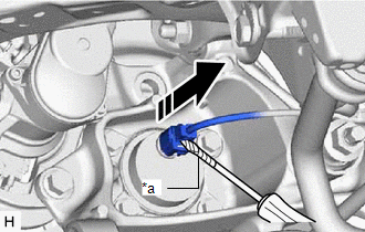
| (a) Disconnect the No. 2 parking brake wire assembly connector from the parking brake actuator assembly. NOTICE:
|
|

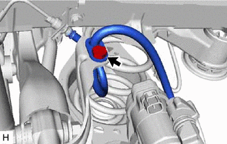
| (b) Using a screwdriver with its tip wrapped with protective tape, disconnect the No. 2 parking brake wire assembly connector from the rear axle hub and bearing assembly. NOTICE: Be careful not to damage the rear axle hub and bearing assembly or connector cover. |
|
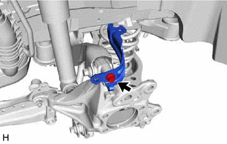
| (c) Remove the nut, disengage the 2 clamps and separate the No. 2 parking brake wire assembly from the rear flexible hose bracket and rear trailing arm assembly. |
|
.png)
7. SEPARATE NO. 2 PARKING BRAKE WIRE ASSEMBLY (w/ AVS)
| (a) Disconnect the No. 2 parking brake wire assembly connector from the parking brake actuator assembly. NOTICE:
|
|
| (b) Using a screwdriver with its tip wrapped with protective tape, disconnect the No. 2 parking brake wire assembly connector from the rear axle hub and bearing assembly. NOTICE: Be careful not to damage the rear axle hub and bearing assembly or connector cover. |
|
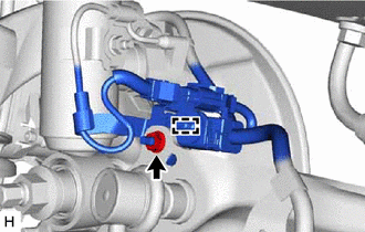
| (c) Disconnect the connector. |
|
.png)
| (d) Remove the nut and disengage the clamp. |
|
| (e) Remove the nut, disengage the clamp and separate the No. 2 parking brake wire assembly from the rear flexible hose bracket and rear trailing arm assembly. |
|
.png)
8. SEPARATE REAR FLEXIBLE HOSE
| (a) Remove the bolt and separate the rear flexible hose from the rear flexible hose bracket. |
|
9. SEPARATE REAR DISC BRAKE CALIPER ASSEMBLY
Click here
10. REMOVE REAR DISC
Click here
11. REMOVE REAR AXLE HUB AND BEARING ASSEMBLY
Click here
12. REMOVE REAR FLEXIBLE HOSE BRACKET
| (a) Remove the bolt and rear flexible hose bracket from the rear axle carrier sub-assembly. |
|
13. REMOVE REAR HEIGHT CONTROL SENSOR SUB-ASSEMBLY LH (w/ Height Control Sensor)
(a) for LH Side:
Click here
14. REMOVE REAR STABILIZER LINK ASSEMBLY
Click here
15. REMOVE REAR COIL SPRING
Click here
16. REMOVE REAR LOWER COIL SPRING INSULATOR
Click here
17. REMOVE REAR NO. 1 SUSPENSION ARM ASSEMBLY
Click here
18. REMOVE REAR AXLE CARRIER SUB-ASSEMBLY
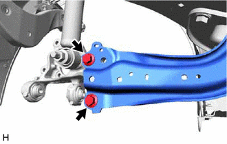
| (a) Loosen the 2 bolts of the rear trailing arm assembly. |
|
| (b) Loosen the nut of the rear shock absorber assembly. NOTICE: Hold the rear axle carrier pin while rotating the nut. |
|

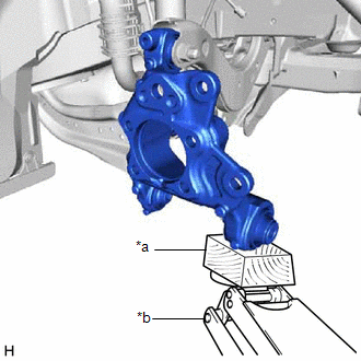
| (c) Using a jack and wooden block, support the rear axle carrier sub-assembly. NOTICE:
|
|
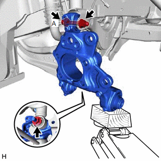
| (d) Loosen the bolt (A). NOTICE: Because the nut has its own stopper, do not turn the nut. Loosen the bolt with the nut secured. |
|
(e) Remove the 2 bolts and separate the rear trailing arm assembly from the rear axle carrier sub-assembly.
(f) Remove the nut and plate washer, and separate the rear shock absorber assembly from the rear axle carrier sub-assembly.
NOTICE:
Hold the rear axle carrier pin while rotating the nut.
(g) Remove the bolt (A), nut and rear axle carrier sub-assembly from the rear upper control arm assembly.
NOTICE:
Because the nut has its own stopper, do not turn the nut. Loosen the bolt with the nut secured.
READ NEXT:
 Components
COMPONENTS ILLUSTRATION *1 NO. 2 PARKING BRAKE WIRE ASSEMBLY *2 REAR AXLE HUB AND BEARING ASSEMBLY *3 REAR AXLE SHAFT NUT *4 REAR DISC *5 REAR DISC BRAKE CALIPER ASSEMBLY *
Installation
INSTALLATION CAUTION / NOTICE / HINT HINT:
Use the same procedure for the RH side and LH side.
The following procedure is for the LH side.
PROCEDURE 1. TEMPORARILY INSTALL REAR AXLE CARRIER SU
SEE MORE:
Cleaning the hybrid battery (traction
battery) air intake vent and
filter
To prevent the fuel economy from
being affected, visually inspect the
hybrid battery (traction battery) air
intake vent periodically for dust and
clogs. If it is dusty or clogged or if
"Maintenance Required for Traction
Battery Cooling Parts See
Owner's Manual" is displayed on
the multi-info
How To Proceed With Troubleshooting
CAUTION / NOTICE / HINT HINT:
Use the following procedure to troubleshoot the sliding roof system.
*: Use the Techstream.
PROCEDURE 1. VEHICLE BROUGHT TO WORKSHOP
NEXT 2. CUSTOMER PROBLEM ANALYSIS HINT:
In troubleshooting, confirm that the problem sympto
