Lexus ES: Components
COMPONENTS
ILLUSTRATION
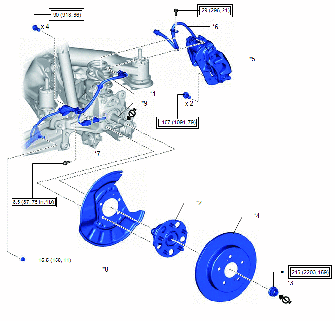
| *1 | NO. 2 PARKING BRAKE WIRE ASSEMBLY | *2 | REAR AXLE HUB AND BEARING ASSEMBLY |
| *3 | REAR AXLE SHAFT NUT | *4 | REAR DISC |
| *5 | REAR DISC BRAKE CALIPER ASSEMBLY | *6 | REAR FLEXIBLE HOSE |
| *7 | REAR SKID CONTROL SENSOR | *8 | REAR DISC BRAKE DUST COVER SUB-ASSEMBLY |
| *9 | REAR DRIVE SHAFT ASSEMBLY | - | - |
.png) | Tightening torque for "Major areas involving basic vehicle performance such as moving/turning/stopping": N*m (kgf*cm, ft.*lbf) | ● | Non-reusable part |
.png) | Do not apply lubricants to the threaded parts | - | - |
ILLUSTRATION
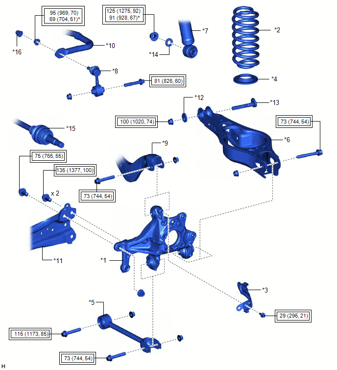
| *1 | REAR AXLE CARRIER SUB-ASSEMBLY | *2 | REAR COIL SPRING |
| *3 | REAR FLEXIBLE HOSE BRACKET | *4 | REAR LOWER COIL SPRING INSULATOR |
| *5 | REAR NO. 1 SUSPENSION ARM ASSEMBLY | *6 | REAR NO. 2 SUSPENSION ARM ASSEMBLY |
| *7 | REAR SHOCK ABSORBER ASSEMBLY | *8 | REAR STABILIZER LINK ASSEMBLY |
| *9 | REAR UPPER CONTROL ARM ASSEMBLY | *10 | REAR STABILIZER BAR |
| *11 | REAR TRAILING ARM ASSEMBLY | *12 | NO. 2 CAMBER ADJUST CAM |
| *13 | REAR SUSPENSION TOE ADJUST CAM SUB-ASSEMBLY | *14 | PLATE WASHER |
| *15 | REAR DRIVE SHAFT ASSEMBLY | *16 | CAP |
| | Tightening torque for "Major areas involving basic vehicle performance such as moving/turning/stopping": N*m (kgf*cm, ft.*lbf) | * | For use with a ball joint lock nut wrench |
READ NEXT:
 Installation
INSTALLATION CAUTION / NOTICE / HINT HINT:
Use the same procedure for the RH side and LH side.
The following procedure is for the LH side.
PROCEDURE 1. TEMPORARILY INSTALL REAR AXLE CARRIER SU
Removal
REMOVAL CAUTION / NOTICE / HINT The necessary procedures (adjustment, calibration, initialization, or registration) that must be performed after parts are removed and installed, or replaced during rea
SEE MORE:
Data List / Active Test
DATA LIST / ACTIVE TEST DATA LIST NOTICE: In the table below, the values listed under "Normal Condition" are reference values. Do not depend solely on these reference values when deciding whether a part is faulty or not. HINT: Using the Techstream to read the Data List allows the values or states of
Switch Failure (B2342)
DESCRIPTION This DTC is stored when the sliding roof ECU (sliding roof drive gear assembly) detects that the panoramic moon roof switch (map light sub-assembly) is stuck for 30 seconds or more. DTC No. Detection Item DTC Detection Condition Trouble Area B2342 Switch Failure Sliding
