Lexus ES: Installation
INSTALLATION
CAUTION / NOTICE / HINT
NOTICE:
This procedure includes the installation of small-head bolts. Refer to Small-Head Bolts of Basic Repair Hint to identify the small-head bolts.
Click here .gif)
PROCEDURE
1. INSTALL VACUUM PUMP ASSEMBLY
(a) When reusing the vacuum pump assembly:
| (1) Install a new No. 1 vacuum pump O-ring to the vacuum pump assembly. |
|
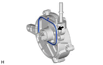
| (b) Install the vacuum pump assembly so that the coupling teeth of the vacuum pump assembly and groove of the camshaft are engaged. NOTICE:
|
|
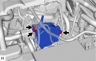
| (c) Using an 8 mm socket wrench, install the vacuum pump assembly with the 3 bolts. Torque: 10 N·m {102 kgf·cm, 7 ft·lbf} NOTICE: After installation, check that there are no gaps between the matching surfaces and that the vacuum pump assembly is not installed at an angle. |
|
2. INSTALL ENGINE WIRE
(a) Engage the 2 clamps to install the engine wire.
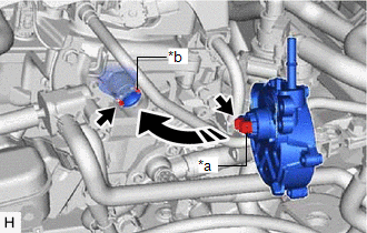
3. CONNECT NO. 1 VACUUM HOSE CONNECTOR
(a) Align the No. 1 vacuum hose connector with the vacuum pump assembly, and push them together until the No. 1 vacuum hose connector makes a "click" sound.
NOTICE:
- Check that there is no foreign matter on the connecting parts.
- After connecting the No. 1 vacuum hose connector, check that the vacuum pump assembly and No. 1 vacuum hose connector are securely connected by pulling on them.
4. INSPECT VACUUM PUMP OPERATION
Click here
READ NEXT:
 On-vehicle Inspection
ON-VEHICLE INSPECTION PROCEDURE 1. OPERATION CHECK (a) Disconnect the No. 1 vacuum hose connector from the vacuum pump assembly. Click here (b) Connect the hose of the vacuum gauge to the vacuum
Reassembly
REASSEMBLY PROCEDURE 1. CLEAN VACUUM PUMP HOUSING (a) Clean the inside surface of the vacuum pump housing. 2. INSTALL VACUUM PUMP ROTOR (a) Clean the vacuum pump rotor. (b) Apply engine oil to the are
Removal
REMOVAL CAUTION / NOTICE / HINT NOTICE: This procedure includes the removal of small-head bolts. Refer to Small-Head Bolts of Basic Repair Hint to identify the small-head bolts. Click here PROCEDURE
SEE MORE:
Components
COMPONENTS ILLUSTRATION *1 REAR ENGINE OIL SEAL *2 NO. 1 CRANKSHAFT POSITION SENSOR PLATE *3 DRIVE PLATE AND RING GEAR SUB-ASSEMBLY *4 REAR DRIVE PLATE SPACER N*m (kgf*cm, ft.*lbf): Specified torque ● Non-reusable part MP grease Adhesive 1324 ★ Pr
Removal
REMOVAL CAUTION / NOTICE / HINT HINT:
Use the same procedure for the RH side and LH side.
The following procedure is for the LH side.
PROCEDURE 1. REMOVE NO. 2 DOOR TRIM PAD Click here 2. REMOVE MULTIPLEX NETWORK MASTER SWITCH ASSEMBLY WITH FRONT DOOR UPPER ARMREST BASE PANEL (for Driver
